Signal Processing
450Hz Venturi bridge signal generator circuit
Published:2011/5/25 6:06:00 Author:Christina | Keyword: 450Hz, Venturi, bridge signal, generator | From:SeekIC

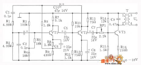
The 450Hz Venturi bridge signal generator circuit, also called the RC oscillator, the circuit is as shown. The oscillator is composed of the VTl, VT2, the feedback network Rl, R2 and the C1、C2. The negative feedback which is composed of the R6、R9 and Cl0 keeps the stabilization of the amplitude and the frequency. The transistor VTl's DC bias resistor are the R3, R4, R7, R8 and R9. The R5 is the input addition resistor, it improves the input impedance. The Rl0, Rll, Rl2 and Rl3 are the DC bias resistor of VT2. VT3 is the power output stage, the output signal gets through the frequency selection networks C9 and L1-2, then output by the transformer T's secondary stage L3-4. The transistor VTl~VT3:3DG128、β=50~70. The capacitor Cl, C2: CM0-100V-50000pF, the measurement error ±0.3%. The thermistor RT: RR527B uses the 2.2V, 12mA.
Reprinted Url Of This Article:
http://www.seekic.com/circuit_diagram/Signal_Processing/450Hz_Venturi_bridge_signal_generator_circuit.html
Print this Page | Comments | Reading(3)

Article Categories
power supply circuit
Amplifier Circuit
Basic Circuit
LED and Light Circuit
Sensor Circuit
Signal Processing
Electrical Equipment Circuit
Control Circuit
Remote Control Circuit
A/D-D/A Converter Circuit
Audio Circuit
Measuring and Test Circuit
Communication Circuit
Computer-Related Circuit
555 Circuit
Automotive Circuit
Repairing Circuit
Code: