
Signal Processing
Index 179
One-way Amplitude Limiting Circuit
Published:2011/5/16 20:48:00 Author:Sharon | Keyword: One-way, Amplitude Limiting
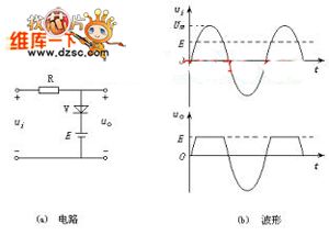
What shows in the figure is the One-way Amplitude Limiting Circuit. It's a circuit that can limit the amplitude of output signal. (View)
View full Circuit Diagram | Comments | Reading(1209)
RC Sine Wave Generator Circuit Composed of LM741CN
Published:2011/5/17 7:12:00 Author:Joyce | Keyword: RC, Sine Wave , Generator Composed of LM741CN
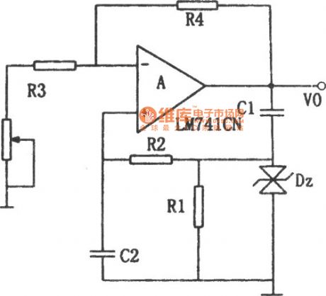
As shown in th (View)
View full Circuit Diagram | Comments | Reading(708)
555 light turn-off reminder circuit
Published:2011/5/16 6:17:00 Author:Christina | Keyword: light, turn-off, reminder

The 555 light turn-off reminder circuit is as shown. This circuit is composed of the monostable delay circuit, driver circuit, buzzer, LED.etc. And the monostable delay circuit's (composed of the 555 and R1, C3) output signal controls the rear circuit.
Power supply of the direction light relay gets through the diode and adds to the pin-8 of 555, this makes the capacitor C3 to be charged through R1. Pin-6's voltage level increases by charging, when pin-6's voltage level gets to 2/3VDD (about 1-minute delay), 555 overturns, the low level voltage of pin-3 makes the BG to conduct. The corresponding LED turns on, and the buzzer starts working, the sound and light signals remind the driver to turn off the light.
(View)
View full Circuit Diagram | Comments | Reading(1790)
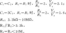
automobile-voltage monitoring circuit
Published:2011/5/15 6:16:00 Author:chopper | Keyword: automobile-voltage, monitoring circuit
This circuit is applied to monitor the 12V power supply voltage of automobile to make sure the voltage is right.If the voltage is between 12V and 14.5V,it is regular;if the voltage is lower than 12V or higher than 14.5V,the indicator will turn on.A1,A2 is a indicator comparator,which is used to adjust potentiometer W1,W2.When power supply voltage is higher than 14.5V,B will turn on;When the voltage is lower than 12V,A will turn on;two of them is dark.
(View)
View full Circuit Diagram | Comments | Reading(494)
Sterilizer electronic control circuit
Published:2011/5/15 1:44:00 Author:John | Keyword: Sterilizer
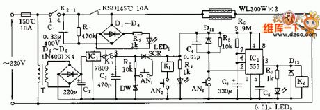
The sterilizer makes the use of infrared heating circuit theory. The sterilizer creates a high-temperature situation in a closed cabinet, when it is used for tableware disinfection. Its circuit is shown below.
Electric control circuit includes the AC step-down voltage regulator circuit, infrared heating circuit and timing control circuit and so forth. Single-phase AC power is transmitted from temperature limit fuses FU (10A, 150 ℃) to the primary transformer T. Then, the AC power is through the processing of step-down, rectifier and regulator. The output DC voltage achieves 9V. Such voltage would get to the anode of a single SCR through the normally closed contacts K1 (1-3). (View)
View full Circuit Diagram | Comments | Reading(991)
remote-control fan circuit
Published:2011/5/17 5:11:00 Author:chopper | Keyword: remote-control fan

View full Circuit Diagram | Comments | Reading(855)
Ward Caller One
Published:2011/5/14 6:05:00 Author:Felicity | Keyword: Ward Caller,

When the call buttons S1-S3 are not pressed, LED vl1-vl3 are all off. Oscillator A and B are both in the stop state lacking of work voltage, and the speaker BL is quiet.
When one of the call buttons is pressed, +6 voltage is provided to oscillator A and B through the button and the diode connected to it. And the BL issues a Du, du calling sound. At the same time while the button is pressed, the LED of the same branch is on.
Adjusting the resistance of RP1 can change the pitch of the calling sound.
Adjusting the resistance of RP2 can change the volume of BL. (View)
View full Circuit Diagram | Comments | Reading(427)
Sine Wave Generator Circuit
Published:2011/5/17 1:44:00 Author:Robert | Keyword: Sine Wave, Generator

The Sine Wave Generator Circuit is shown below.
(View)
View full Circuit Diagram | Comments | Reading(721)
Ward Caller Three
Published:2011/5/14 7:07:00 Author:Felicity | Keyword: Ward Caller,
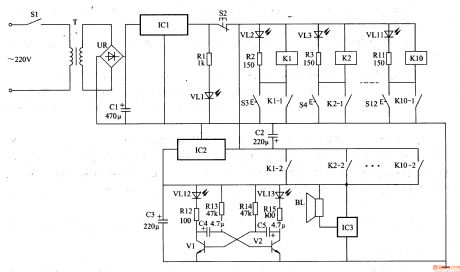
When the control buttons S3-S12 are not pressed, K1-K10 are both in the release state, Vl2-VL13 are off, BL is noiseless.
When one of the control buttons is pressed, the relay in this branch closes and is self-locked, and the LED shows the bed number. At the same time, the other group normally open contact closes to make the acoustic and optical alarm circuit work. VL12 and VL13 shines and BL sends a music alarm to remind the medical personnel to deal with it in time.
In practice, the number of relays, buttons, LEDs or current-limiting resistors can be adjusted according to the actual demand.
(View)
View full Circuit Diagram | Comments | Reading(447)
Ward Caller Two
Published:2011/5/14 6:41:00 Author:Felicity | Keyword: Ward Caller ,
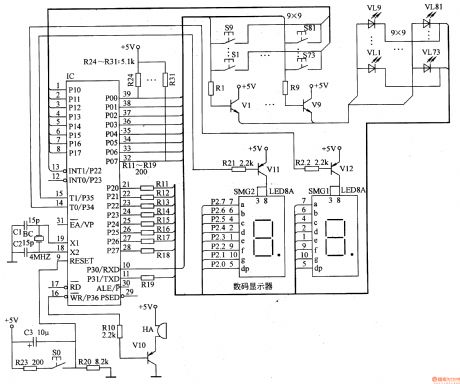
When one button of S1-S81 is pressed, the inside program control circuit of the IC detects the bed number represented by the button number. And the pin 16 is at low level to make V10 close, and HA sends out a call. Pin 15 and pin 14 are at low level to make V11 or V12 close. Pin 21-28 output signals to drive the digital code scope to display the calling bed number while the LED corresponding to the pressed button is on.
Once the reset button S0 is pressed, the lighted LED will be off, and the number displayed on the digital code scope will disappear, and HA will stop. (View)
View full Circuit Diagram | Comments | Reading(452)
main control panel of air conditioner circuit
Published:2011/5/15 6:22:00 Author:chopper | Keyword: main control panel, air conditioner

View full Circuit Diagram | Comments | Reading(646)
MAX1626 Fan speed control circuit
Published:2011/5/15 5:23:00 Author:John | Keyword: Fan
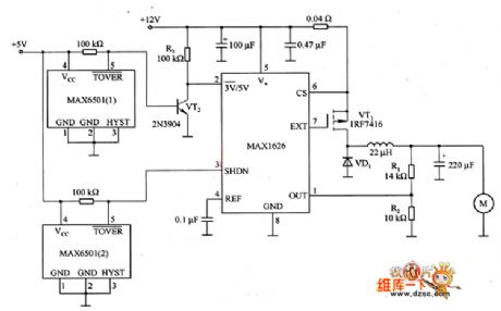
The figure is the speed control circuit of fan, which is mainly constituted by the MAX1626. This circuit reduces the noise and power consumption of the computer, the temperature controller and alarm systems. It achieves by utilizing the closure and output voltage of MDH626. The logic level voltage is added to pin 2 (3V/5V) and pin 3 (SHDN). At the same time, appropriate feedback resistor (Rl and R2) are selected to set the output voltage. In general, low output voltage U (01) (here for 8V) is determined by the sub-decision resistors R1 and R2. And the high output voltage U (02) (here for 12V) is determined by voltage on output end of the chip (pin 4).
(View)
View full Circuit Diagram | Comments | Reading(796)
The priciple circuit of Volga 3102
Published:2011/5/12 22:26:00 Author:Borg | Keyword: priciple circuit, Volga

the principle circuit of Volga 3102 is as shown in Figure 1 to Figure 6.
12-spark piston; 13-power igniter. 14-additional resistence of ignition systems; 36-oil instrument; 37-igniting sensor; 45-oil instrument sensor; 46-indicator test switch; 71-current instrument; 73-ignition relay; 74-voltage adjuster; 78-vacuum switch; 79-power control unit; 80-solenoid valve; 82-electric generator; 84-air solenoid valve of float chamber; 85-starting relays; 86-igniting coil; 87-battery; 88-electricity distributor. (View)
View full Circuit Diagram | Comments | Reading(668)
The principle function parameter circuit of Alto SC7080
Published:2011/5/12 22:00:00 Author:Borg | Keyword: parameter circuit, Alto


(View)
View full Circuit Diagram | Comments | Reading(571)
CC4527-BCD series multiplier integrated circuit diagram
Published:2011/5/11 3:33:00 Author:Fiona | Keyword: multiplier integrated


CC4527 is a BCD series multiplier integrated circuit and a universal digital device.It's widely used in various digital signal processing circuit, such as digital instrumentation, communications systems etc.1. The pin functions
CC4527 integrated circuits use 6-pin dual in-line package.The pin functions are listed in Table 1.
Table 1 CC4527 integrated circuits' pin functions
2. Typical application circuit
Evenly spaced type of frequency ratio control circuit posed by the CC4527 integrated circuits is shown in Figure 1.
Figure 1 Evenly spaced frequency ratio control circuit posed by the CC4527 integrated circuits (View)
View full Circuit Diagram | Comments | Reading(597)
CAT2404P memory integrated circuit diagram
Published:2011/5/11 3:34:00 Author:Fiona | Keyword: memory


CAT2404P is a piece of memory memory integrated circuits.It's widely used in color TV, air conditioning control circuits, audio systems, DVD players control system.
1. Features
CAT2404P integrated circuits' in-circuit is mainly composed by the internal circuitry memory matrix, the data input / output interface circuit, the clock pulse processing circuits, test circuits, and other auxiliary functions circuit etc.
2. pin functions and data
CAT2404P integrated circuits use 8-pin dual in-line package, the pin functions are shown in Figure 1, the typical operating voltage are listed in Table 1.
Figure 1 CAT2404P integrated circuits' pin functions
Table 1 The typical operating voltage of CAT2404P integrated circuits
(View)
View full Circuit Diagram | Comments | Reading(438)
Medical call receiver circuit
Published:2011/5/11 7:04:00 Author:Christina | Keyword: Medical, call receiver


The medical call receiver circuit can avoid to miss the turn voice of the patients, in the daytime, this receiver works by itself, it automatically cuts off the floodlight part. At night, the receiver and lighting signal is sent by the patients simultaneously. When you press the call switch, the transformer X1's primary stage will connect to the AC power, the secondary voltage is rectified and filtered by the circuit, the output DC voltage sends to the VT1 collector through R1. In the daytime, the photoconductive resistance LDR1 shows the low impedance state by the light ray, VT1 conducts and it's collector shows the low-level voltage, so the thyristor BT136 don't work, you can only hear the call bell, lighting signal is in the invalid state. At night, LDR1 is in the high impedance state for the dark, so after you press S1, VT1 cuts off to make the positive DC voltage can be charged through the R1 and R3. VD3 can makes the constant DC positive bias voltage to trigger the BT136, so lamp L1 turns on, and you can hear the ringtone at night and see the turning light signal.
(View)
View full Circuit Diagram | Comments | Reading(1358)
The Wiring Circuit(a) of Volga 3102
Published:2011/5/12 7:50:00 Author:Borg | Keyword: Wiring Circuit, Volga

Figure 7 The Wiring Circuit(a) of Volga 3102
1-headlight; 2-width lamp; 3-steering lamp; 4-fog lamp; 5-loudspeaker; 6-working lamp outlet; 7-loudspeaker relay; 8-wiper motor; 9-wiper switch; 10-washer switch; 11-loudspeak buttom; 12-spark piston; 13-electrical igniter; 14-additional resistence of igniting system; 15-water temperature sensor; 16-engine overheat warnign switch; 18-low oil pressure warning switch; 19-brake failure indicator switch; 2-wiper relay;72-engine room lamp (View)
View full Circuit Diagram | Comments | Reading(480)
The principle circuit of Volga 3102 headlights
Published:2011/5/12 6:59:00 Author:Borg | Keyword: principle circuit, Volga

Figure 16-6 The principle circuit of Volga 3102 headlights
1-headlight; 24-high beam indicator; 39-simmer switch; 65-light switch; 70-headlight relay (View)
View full Circuit Diagram | Comments | Reading(577)
The Priciple Circuit of Volga 3102 Cigarette Lighter,Loudspeaker and Room Lamp
Published:2011/5/12 7:10:00 Author:Borg | Keyword: Volga, cigarette lighter, loudspeaker, room lamp

Figure 4 The Priciple Circuit of Volga 3102 Cigarette Lighter,Loudspeaker and Room Lamp
5-loudspeaker; 6-stand-by outlet; 7-loudspeaker relay; 11-loudspeaker buttom; 12-clock; 42-cigrette lighter; 43-right door lamp; 44-left door lamp; 49-brake lamp; 52-ceiling light; 53-(left, right)ceiling light; 54-staff chamber lamp; 67-brake lamp switches; 72-engine room lamp (View)
View full Circuit Diagram | Comments | Reading(468)
| Pages:179/195 At 20161162163164165166167168169170171172173174175176177178179180Under 20 |
Circuit Categories
power supply circuit
Amplifier Circuit
Basic Circuit
LED and Light Circuit
Sensor Circuit
Signal Processing
Electrical Equipment Circuit
Control Circuit
Remote Control Circuit
A/D-D/A Converter Circuit
Audio Circuit
Measuring and Test Circuit
Communication Circuit
Computer-Related Circuit
555 Circuit
Automotive Circuit
Repairing Circuit