Signal Processing
Ward Caller Three
Published:2011/5/14 7:07:00 Author:Felicity | Keyword: Ward Caller, | From:SeekIC

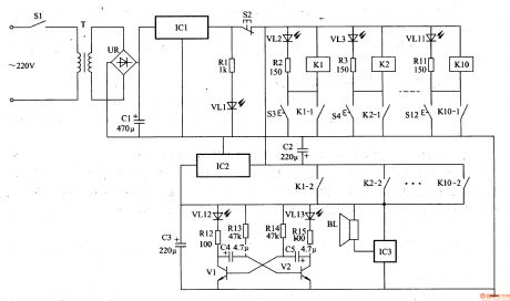
When the control buttons S3-S12 are not pressed, K1-K10 are both in the release state, Vl2-VL13 are off, BL is noiseless.
When one of the control buttons is pressed, the relay in this branch closes and is self-locked, and the LED shows the bed number. At the same time, the other group normally open contact closes to make the acoustic and optical alarm circuit work. VL12 and VL13 shines and BL sends a music alarm to remind the medical personnel to deal with it in time.
In practice, the number of relays, buttons, LEDs or current-limiting resistors can be adjusted according to the actual demand.
Reprinted Url Of This Article:
http://www.seekic.com/circuit_diagram/Signal_Processing/Ward_Caller_Three.html
Print this Page | Comments | Reading(3)

Article Categories
power supply circuit
Amplifier Circuit
Basic Circuit
LED and Light Circuit
Sensor Circuit
Signal Processing
Electrical Equipment Circuit
Control Circuit
Remote Control Circuit
A/D-D/A Converter Circuit
Audio Circuit
Measuring and Test Circuit
Communication Circuit
Computer-Related Circuit
555 Circuit
Automotive Circuit
Repairing Circuit
Code: