
Signal Processing
Index 164
The frequency multiplier composed of XR-S200
Published:2011/6/17 20:14:00 Author:Borg | Keyword: frequency multiplier

View full Circuit Diagram | Comments | Reading(501)
The 3-way frequency circuit of symmetric output(74LS109 and 74LS113)
Published:2011/6/17 20:25:00 Author:Borg | Keyword: 3-way frequency, symmetric output
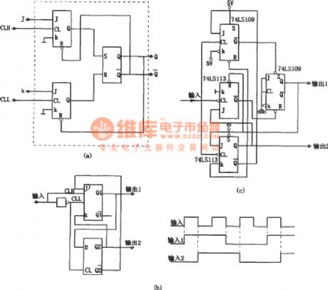
In the figure is the 3-way frequency circuit of symmetric output. Usually, when we use common counter to odd-split the digital pulse, even the input is the symmetric signal, the output won't be the splitting frequency of 50% duty cycle, the reason is that all the internal triggers are motivated by the rising edge (or the dropping edge). To solve the problem, we can use a J and K, two JK triggers that are motivated by the clock, see as figure (a). The circuit includes two JK triggers and a RS trigger. (View)
View full Circuit Diagram | Comments | Reading(1128)
The continual signal frequency splitting circuit composes of CC4013
Published:2011/6/17 20:40:00 Author:Borg | Keyword: signal frequency, splitting circuit
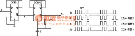
In the figure is the continual signal frequency splitting circuit composes of CC4013. This circuit consists of a double frequency splitter circuit and a single steady circuit, which can fulfill the splitting function with external signals, but when the input signal is halt, the circuit can come back to the 0 state automatically. The single steady time can be adjusted according to requirements. The input signal is in the terms of continual bundles. After it crosses the 1st stage frequency splitter, though the pulse in the bundle is split, the interval between bundles may be in the low LEV (if the number of the pulse in the bundle is even). (View)
View full Circuit Diagram | Comments | Reading(518)
The sine wave frequency-halving circuit (μA747 and μA795)
Published:2011/6/17 20:54:00 Author:Borg | Keyword: sine wave, frequency-halving circuit
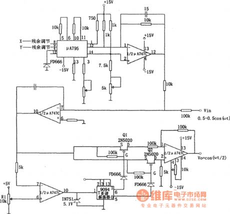
To an ordinary digital frequency splitting circuit, the weakness is that it can't maintain the former sine waveform. If the sine wave output is needed, we can add a additional filter or the like, see as the circuit. In the circuit, the integrated circuits of μA795 and μA747C compose the standard square root circuit. The output of circuit the positive square root of the input voltage absolute value. When the input ±0.5cosωt, the output is cos( ωt/2). The trigger 9094, analog switches (Q1 and Q2) and half of the computing amplifier μA747 consist of the absolute value removing circuit. (View)
View full Circuit Diagram | Comments | Reading(837)
The 10~100MHz frequency splitter composed of MC1013
Published:2011/6/17 21:28:00 Author:Borg | Keyword: frequency splitter
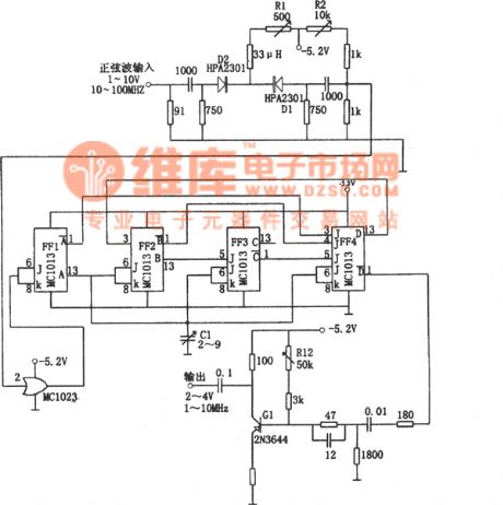
The working frequency of the circuit can reach 100MHz, the heat loading diode limiters (D1 and D2) can transport the 10V signals to the gate circuit MC1023 without any loss. The changeable resistor R1 is the bias point that controls D1 and D2, which makes the positive voltage of D1 be -3.2v. The amplitude limiter outputs a signal that is rectified by the high speed pulse driver MC1023, and the signal is delivered to the 120MHz J-K trigger FF1 and split into two. The output of FE1 is put into the dividing 5 circuits (FF2,FF3 and FF4), then the output drive transistor Q1 of FF4 generates a square wave whose amplitude is 2~4v and frequency is 1~10MHz. (View)
View full Circuit Diagram | Comments | Reading(792)
The 1GHz preset frequency splitter composed of SP6168
Published:2011/6/17 21:39:00 Author:Borg | Keyword: frequency splitter
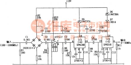
In the figure is the 1GHz preset frequency splitter. The splitter is powered by a +15v single power supply, whose sensitivity is 30mVrms, and it has a dynamic range of 40dB, its working frequency is 100~1000MHz. In the figure, the input signal is coupled to the diode bridge amplitude limiter by the capacitor, the peak value of the limiter output signal is 100mV, which is amplified by the wide frequency calculating amplifier A1, and then coupled to the 4 point frequency circuit by C3. R6 is the output terminal loading of A1, R7 is the input bias resistor of R7. The output is coupled to the 5-point frequency by the capacitor. (View)
View full Circuit Diagram | Comments | Reading(414)
The digit controlled frequency splitter composed of MC4018
Published:2011/6/17 21:50:00 Author:Borg | Keyword: frequency splitter

In the figure is the digit controlled frequency splitter and Figure (a) is the principle circuit. The circuit can set any splitting constant and output a square wave. To a random even number N, the N can be written as N=2M, and to a random odd number, which can be represented as N=2M+1. If N is represented in the binary way, the minimum binary bit may be removed and it gets M, so the frequency splitting constant can be controlled by the binary number. Therefore, to a certain N, we can design a M frequency splitter. For example, if N=181, then the M added on the splitter will be 90. (View)
View full Circuit Diagram | Comments | Reading(511)
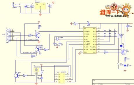
The learning infrared remote control terminal circuit
Published:2011/6/19 20:04:00 Author:qqtang | Keyword: infrared, remote control
View full Circuit Diagram | Comments | Reading(568)
The electric rat exterminator circuit (2)
Published:2011/6/19 20:01:00 Author:qqtang | Keyword: rat exterminator
View full Circuit Diagram | Comments | Reading(648)
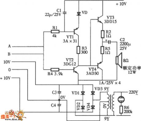
The electric rat exterminator circuit (1)
Published:2011/6/19 20:00:00 Author:qqtang | Keyword: rat exterminator
View full Circuit Diagram | Comments | Reading(709)
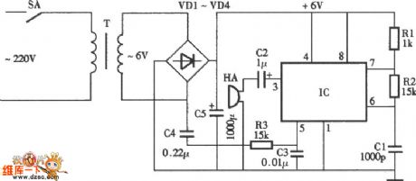
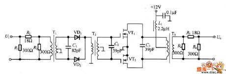
High-voltage pulse generator
Published:2011/6/16 5:47:00 Author:Lucas | Keyword: High-voltage, pulse generator

The circuit is shown as the chart, it uses the 6V ~ 12V DC power supply to produce high-voltage pulse. In the circuit, the transistors VTl, VT2 constitute an oscillator to produce a DC pulse voltage with the frequency in 3Hz, and it has the primary coil of booster with the output transformer ratio in 6V: 240V, and after each pulse ends, the secondary coil of corresponding transformer will generate a high voltage level. Pulse repetition frequency can be selected by adjusting C2, Rl. When the circuit is used in the baton, it can use lead-acid batteries.
(View)
View full Circuit Diagram | Comments | Reading(51)
The sine wave generating circuit
Published:2011/6/16 6:03:00 Author:Seven | Keyword: sine wave, generating

View full Circuit Diagram | Comments | Reading(709)
The oscillating circuit composed of crystal and NOR gate
Published:2011/6/16 6:17:00 Author:qqtang | Keyword: oscillating circuit, NOR gate

In the figure is the oscillating circuit composed of crystal and NOT gate. In the circuit, X is the 1MHz crystal, and it connects with 10 frequency splitting circuits, which has 6 stages of parallel connections. Therefore, it can pick out signals of different frequencies from different output terminals, i.e A terminal outputs 100KHz frequency, B outputs 10KHz, C outputs 1KHz, D outputs 100 Hz, E outputs 10Hz, F outputs 1Hz and so on.
(View)
View full Circuit Diagram | Comments | Reading(701)
The frequency doubler circuit of high but few harmonic waves
Published:2011/6/16 6:29:00 Author:qqtang | Keyword: frequency doubler, harmonic waves
In the figure is the frequency doubler circuit of high but few harmonic waves. When the high frequency signal can'T be got from the crystal circuit directly, this circuit can be fixed in the oscillating circuit and high frequency signals can be got. As there is a modulation circuit, the frequency band turns narrow, but the high frequency output signals are pure. When the input is -2dBm, an output voltage of 6dBm can be got, the distortion of the high frequency harmonic wave is lower than -6dB.
(View)
View full Circuit Diagram | Comments | Reading(820)
555 TV square grid generator circuit
Published:2011/6/15 3:58:00 Author:TaoXi | Keyword: 555, TV, square grid, generator circuit
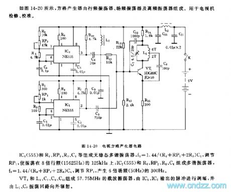
As the figure 14-20 shows, the square grid generator is composed of the line frequency oscillator, the field frequency oscillator and the high frequency oscillator, it can be used in the overhaul and calibration of the TVs.
The astable multivibrator is composed of the IC1(555) and R1, RP1, R3, C1, the f1=1.44/(R1+RP1+2R3)C1, by adjusting RP1, we can make the oscillation frequency on the 125kHz which is 8 times of the line frequency; the multivibrator is composed of the IC2(555) and R6, RP2, R8, C4, the f2=1.44/(R6+RP2+2R8)C4, by adjusting RP2, we can make the oscillation frequency on the 300kHz which is 6 times of the line frequency.
The 57.75MHz wave-carrier oscillator is composed of the VT1 and L1, C7, C8, C12, it is adjusted by the output pulses of IC1 and IC2, and it radiates by the L1, C7 oscillation loop.
(View)
View full Circuit Diagram | Comments | Reading(1005)
555 electronic musical instrument additional combo audio circuit
Published:2011/6/15 4:22:00 Author:TaoXi | Keyword: 555, electronic musical instrument, additional, combo audio circuit
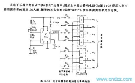
If we add this combo audio circuit (as the figure 14-38 shows) to the automatic rhythm generator of the electronic musical instruments, we can meet the the requirements of players to add the combo audio of drum and cymbals to make the performance effect more perfect.
As the figure shows, the astable multivibrator is composed of the 555 and R1, RP1, R2, C1, the oscillation period T=0.693(R1+RP1+2R2)C1, the oscillation period sound effects are adjustable. If you press different K(K1~K7), you can get the corresponding combo sound. By adjusting RP1, you can change the frequency of the combo sound.
(View)
View full Circuit Diagram | Comments | Reading(1632)
555 multi-function sound generator
Published:2011/6/15 4:58:00 Author:TaoXi | Keyword: 555, multi-function, sound generator
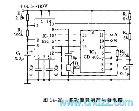
As the figure 14-28 shows, the sound generating circuit is composed of the 556 and CD4051, this circuit can produce the single, dual-tone and rhythm-style sound.
The astable oscillator is composed of the IC's left part (1/2 556) and R1, R2, C1, f=1.44/(R1+2R2)C1, the oscillation frequency of the figure parameter is 2Hz, it's output port pin-5 is connected with the public input / output port (pin-3) of IC2, IC2 is the 8-channel analog switch CD4051, the port A and port B control one channel's connection of this switch.
The sound oscillator is composed of the IC1(1/2 556) and the R3, R4, C2. When A=0,B=0, this circuit outputs the double audio frequencies sound signal; when A=1,B=1, the 2Hz signal which is produced by the left part of IC1 does not play the control function until it outputs the single-tone with the frequency of 900Hz.
(View)
View full Circuit Diagram | Comments | Reading(2135)
555 multi-stage electronic metronome circuit
Published:2011/6/15 7:02:00 Author:TaoXi | Keyword: 555, multi-stage, electronic metronome
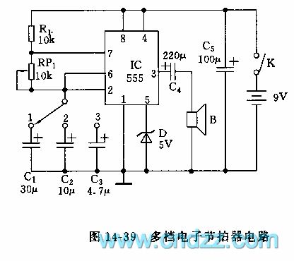
As the figure 14-39 shows, in this circuit the 555 is used as the astable multivibrator. The circuit beat is divided into three stages to be controlled, the oscillation frequency f1=1.44/(R1+RP1)C1, it is about 20-60 beats/min; f2=1.44/(R1+RP1)C2, it is about 60-80 beats/min; f3=1.44/(R1+RP1)C3, it is about 180-540 beats/min; after you know the calculation formula, you can change the charging and discharging time constant RC by yourself according to the actual situation to adjust the frequency or the beat. Also you can increase or decrease the number of stages. In order to make the beat more accurate and the parameters more stable, you need to use the metal film RJ as the resistance, and the electrolytic capacitor need to have the features of small leakage of electricity and high voltage capacitance.
(View)
View full Circuit Diagram | Comments | Reading(1598)
555 audio signal array display circuit
Published:2011/6/15 7:19:00 Author:TaoXi | Keyword: 555, audio signal, array display
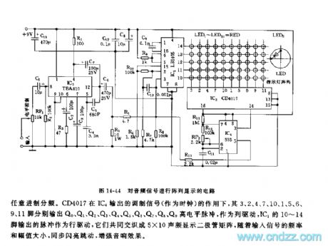
This circuit is composed of the audio signal amplification circuit, the pulse position modulation circuit, the counting circuit, the audio display driver stage array circuit.etc. As the figure 14-44 shows.
The input audio signal adds to the input port pin-8 of IC3(TBA810) through the electrical level adjustment potentiometer RP1. The output amplified signal is divided into two channels, one channel adds to the pin-3 of audio display driver stage IC1(LB1405), another channel adds to the voltage control port pin-5 of the IC4(555) time-base circuit as the pulse position modulation mode sync signal. When there is no input signal, the resonance frequency of 555 is f0=1.44/(R11+2R12+RP2)C11. The resonance frequency of the parameters is 59~61Hz, by adjusting RP2, you can make the resonance in the center frequency f0=60Hz.
(View)
View full Circuit Diagram | Comments | Reading(1850)
555 radio digital frequency displayer circuit
Published:2011/6/14 6:38:00 Author:TaoXi | Keyword: 555, radio, digital, frequency displayer, circuit
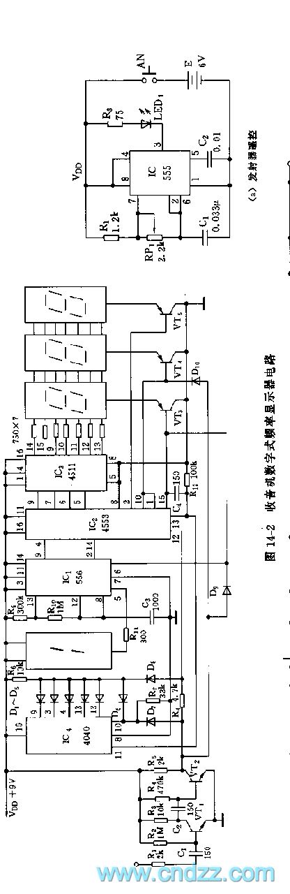
As the figure 14-2 shows, this circuit is composed of four pieces of integrated circuits and four LED luminescence digital tubes to display the frequency of the medium-wave station, it displays the frequency accurately and the circuit is simple.IC1 uses the dual time-base circuit 556, the astable multivibrator is composed of the 1/2 556 and the R9, R10, C3, the oscillation frequency f=1.44/(R9+2R10)C3, it is about 1000Hz, the output of pin-9 adds to IC2's external scanning input port pin-4. Another half of 556 (1/2 556) is connected as the trigger, the output of pin-5 adds to the luminescence digital tube.
The IC2(MC14553) is a BCD code 3-bit counter. The AND gate is composed of the D9 and D10. When the pin-1 and pin-15 have the low electrical level, the VT3 and VT4 conduct.
(View)
View full Circuit Diagram | Comments | Reading(586)
| Pages:164/195 At 20161162163164165166167168169170171172173174175176177178179180Under 20 |
Circuit Categories
power supply circuit
Amplifier Circuit
Basic Circuit
LED and Light Circuit
Sensor Circuit
Signal Processing
Electrical Equipment Circuit
Control Circuit
Remote Control Circuit
A/D-D/A Converter Circuit
Audio Circuit
Measuring and Test Circuit
Communication Circuit
Computer-Related Circuit
555 Circuit
Automotive Circuit
Repairing Circuit