Signal Processing
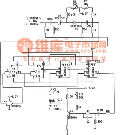
The 10~100MHz frequency splitter composed of MC1013
Published:2011/6/17 21:28:00 Author:Borg | Keyword: frequency splitter | From:SeekIC

The working frequency of the circuit can reach 100MHz, the heat loading diode limiters (D1 and D2) can transport the 10V signals to the gate circuit MC1023 without any loss. The changeable resistor R1 is the bias point that controls D1 and D2, which makes the positive voltage of D1 be -3.2v. The amplitude limiter outputs a signal that is rectified by the high speed pulse driver MC1023, and the signal is delivered to the 120MHz J-K trigger FF1 and split into two. The output of FE1 is put into the dividing 5 circuits (FF2,FF3 and FF4), then the output drive transistor Q1 of FF4 generates a square wave whose amplitude is 2~4v and frequency is 1~10MHz.
Reprinted Url Of This Article:
http://www.seekic.com/circuit_diagram/Signal_Processing/The_10~100MHz_frequency_splitter_composed_of_MC1013.html
Print this Page | Comments | Reading(3)

Article Categories
power supply circuit
Amplifier Circuit
Basic Circuit
LED and Light Circuit
Sensor Circuit
Signal Processing
Electrical Equipment Circuit
Control Circuit
Remote Control Circuit
A/D-D/A Converter Circuit
Audio Circuit
Measuring and Test Circuit
Communication Circuit
Computer-Related Circuit
555 Circuit
Automotive Circuit
Repairing Circuit
Code: