Signal Processing
555 audio signal array display circuit
Published:2011/6/15 7:19:00 Author:TaoXi | Keyword: 555, audio signal, array display | From:SeekIC

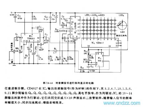
This circuit is composed of the audio signal amplification circuit, the pulse position modulation circuit, the counting circuit, the audio display driver stage array circuit.etc. As the figure 14-44 shows.
The input audio signal adds to the input port pin-8 of IC3(TBA810) through the electrical level adjustment potentiometer RP1. The output amplified signal is divided into two channels, one channel adds to the pin-3 of audio display driver stage IC1(LB1405), another channel adds to the voltage control port pin-5 of the IC4(555) time-base circuit as the pulse position modulation mode sync signal. When there is no input signal, the resonance frequency of 555 is f0=1.44/(R11+2R12+RP2)C11. The resonance frequency of the parameters is 59~61Hz, by adjusting RP2, you can make the resonance in the center frequency f0=60Hz.
Reprinted Url Of This Article:
http://www.seekic.com/circuit_diagram/Signal_Processing/555_audio_signal_array_display_circuit.html
Print this Page | Comments | Reading(3)

Article Categories
power supply circuit
Amplifier Circuit
Basic Circuit
LED and Light Circuit
Sensor Circuit
Signal Processing
Electrical Equipment Circuit
Control Circuit
Remote Control Circuit
A/D-D/A Converter Circuit
Audio Circuit
Measuring and Test Circuit
Communication Circuit
Computer-Related Circuit
555 Circuit
Automotive Circuit
Repairing Circuit
Code: