
Signal Processing
Index 165
555 radio automatic sentence spliting playback circuit
Published:2011/6/14 7:22:00 Author:TaoXi | Keyword: 555, radio, automatic, sentence spliting, playback circuit
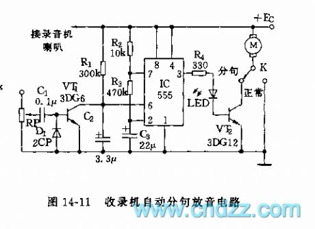
When there is the playback signal, the signal is rectified by D1 to conduct the VT1, and C2 discharges. The 555 is in the set state, the LED turns on, the VT2 conducts, the motor M starts working to send out the sound. When sentence is over, the VT1 cuts off, the C2 is charged by R1, after about 1 second, when the voltage of C2 is higher than the threshold level 2/3VDD, the 555 resets to output the low electrical level, the M stops working. At the same time, the C3 discharges to the disrharge tube of 555 substrate through R3, when the voltage of C3 is lower than 1/3VDD, the 555 sets again, pin-3 has the high electrical level, M stops working. The discharging time tdischarge=1.1R3C3, the tdischarge of the figure parameters is about 10 seconds for the follow reading.
(View)
View full Circuit Diagram | Comments | Reading(427)
555 four octaves tone generator circuit
Published:2011/6/14 7:47:00 Author:TaoXi | Keyword: 555, four octaves, tone generator
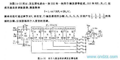
As the figure 14-35 shows, the generator circuit is composed of one piece of 555 and a four-D trigger. The astable multivibrator is composed of the 555 and RP1, R2, C1, the oscillation frequency f=1.44/(RP1+2R2)C1, the frequency can be changed by adjusting the RP1. The trigger D can be used as the frequency divider, S2,S3,S4 and S5 produce the 1/2,1/4,1/8 and 1/16 frequency divisions of the fundamental frequency, so we get four octave tones.
Figure 14-35 The555 four octaves tone generator circuit (View)
View full Circuit Diagram | Comments | Reading(868)
555 infrared remote control eight-channel selection radio circuit
Published:2011/6/14 8:18:00 Author:TaoXi | Keyword: 555, infrared remote control, eight-channel selection, radio
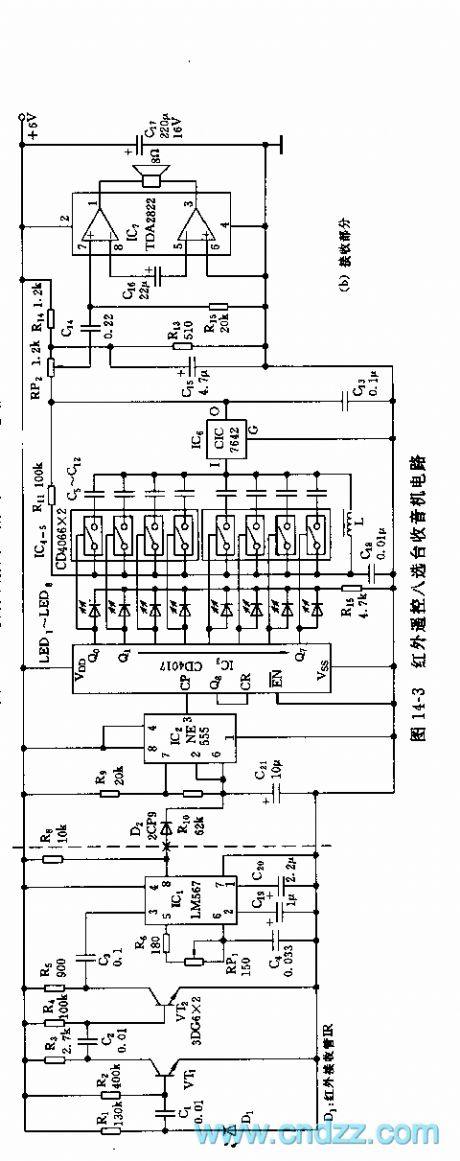
As the figure 14-3 shows, the infrared remote control eight channels radio circuit is composed of the infrared remote control transmitter, the remote control decoder and the channel selection recording part.The remote transmitter is composed of the multivibrator (composed of the 555 and R1, RP1, C1) and the infrared transmitting tube, the oscillation frequency f=1.44/(R1+RP1)C1, the frequency of the figure parameters is about 120kHz, the duty ratio is 67%.
The receiving part is composed of the infrared receiving amplifier, the decoding circuit IC1, the pulse distribution circuit, the electronic switch selective passing radio circuit and the amplifier stage. D1 is the receiving tube which can be used with the launch infrared diode, the VT1 and VT2 are the signal amplification stage. The IC1 uses the PLL audio decoder LM567.
The monostable trigger circuit is composed of the IC2(555) and R9, R10, C21, this circuit outputs the pulse with 1 second pulse width.
(View)
View full Circuit Diagram | Comments | Reading(628)
555 point-frequency TV terminal circuit
Published:2011/6/14 20:28:00 Author:TaoXi | Keyword: 555, point-frequency, TV, terminal circuit

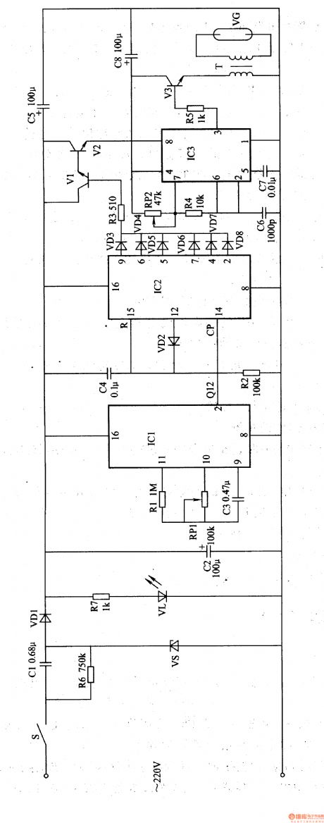
As the figure 14-17 shows, this circuit is composed of the input circuit, the line frequency synchronization generator, the sample-and-hold circuit, the voltage control delay generator and the RF modulator.
The input circuit is composed of the input attenuator RP1 and the emitter follower VT1. The astable multivibrator is composed of the IC2 (555) and RP2, C4.etc, by adjusting RP2, you can make the IC2 to output the pulse waveform which is synchronous as the line scanning frequency 15625Hz, and this pulse is output by pin-3 to add to the trigger port pin-2 of IC1 as the sampling pulse, at last it adds to the e pole of the RF modulator VT2. The sampling and voltage control delay pulse generator is composed of the IC2 (555) and R5, R6, C2.etc.
(View)
View full Circuit Diagram | Comments | Reading(1492)
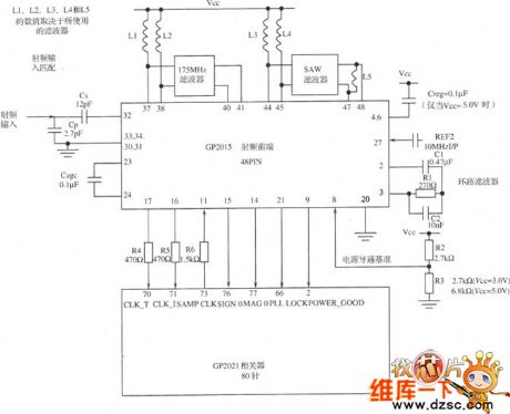
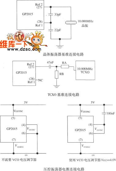
The GPS receiver RF circuit of GP2015
Published:2011/6/13 22:05:00 Author:Seven | Keyword: GPS receiver, RF circuit
View full Circuit Diagram | Comments | Reading(580)
The PLL FM modem circuit
Published:2011/6/13 22:02:00 Author:Seven | Keyword: PLL, FM modem

View full Circuit Diagram | Comments | Reading(2508)
M15M machine core protection circuit
Published:2011/6/12 22:47:00 Author:Christina | Keyword: machine core, protection circuit
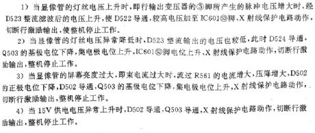
The M15M machine core protection circuit is as shown:
1.When the voltage of the CRT's filament increases, the voltage which is rectified and filted by the D523 increases too, the D522 conducts, the high voltage adds to pin-2 of the IC601, the X-ray protection circuit starts working to cut off the line excitation output, the device stops working.
2.When the voltage of the CRT's filament decreases, the the voltage which is rectified and filted by the D523 decreases too, at this time the D524 conducts, the base port potential of the Q503 decreases, the collector potential increases, the voltage of IC601's pin-52 increases, and the X-ray protection circuit starts working to cut off the line excitation output, the device stops working.
3.When the CRT's brightness is too large, the device stops working.
4.When the 15V power supply voltage increases, the device stops working. (View)
View full Circuit Diagram | Comments | Reading(431)
Voice type logic pen circuit (CD4011) composed of the gate circuit
Published:2011/6/12 22:26:00 Author:Christina | Keyword: Voice type, logic pen, gate circuit
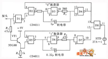
The test result of the shining type logic pen need to be observed by the eyes. Due to the high development of the modern electronic production technology, the soldered dots of the circuit board are very intensive. So you must concentrate on the measure point when you are testing. We make a voice tester, so that our ears can also be used in the testing, this method will greatly improves the testing efficiency. The voice type logic pen which is composed of the NAND gate is as shown in the figure.
(View)
View full Circuit Diagram | Comments | Reading(457)
Ozone Sterilizer(the 6th)
Published:2011/5/19 8:07:00 Author:Felicity | Keyword: Ozone sterilizer,
Work of the Ozone Sterilizer Circuit
The ozone sterilizer circuit consists of Power circuit, oscillator circuit and ozone generator circuit (showed in picture 9-103).
Turn on the Timer Q and the +6V voltage will be produced after the 220V AC voltage is bucked, rectified, rectified and filtered by C1,VS,VD and C2. This voltage will supply IC and ozone generator circuit. When the low-frequency oscillator works the high-frequency oscillator is pulse modulated. Modulated pulse signal goes through R7 to the base added to V and makes V intermittently conducted. In the secondary winding to T generates pulsed high voltage and VG produces ozone in the role of high-frequency high-voltage. (View)
View full Circuit Diagram | Comments | Reading(636)
Ozone sterilizer (the 8th)
Published:2011/5/19 8:01:00 Author:Felicity | Keyword: Ozone sterilizer,
Work of the circuit
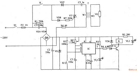
The ozone sterilizer circuit consists of power circuit, timing control circuit, and the ozone generator circuit (showed in picture 9-105).
When we Turn the power switch S the 220V cross voltage is bucked, regulated, rectified and filtered by C8,VS,VDl and CI. And then it produces +l2V voltage. It turns into two parts. One supplies the timing control circuit while the other one lightens VL after being bucked and limited by R7.
The Oscillation signal generated by ICL Internal Oscillator (which consisters of ICL,RL,RPL and C3) is outputed prom pin 2 through internal divider. Then make it Intermittently conducted between V1 and V2. In that way the ozone generator circuit intermittently gets power and works. (View)
View full Circuit Diagram | Comments | Reading(647)
Ozone Sterilizer (the 4th)
Published:2011/5/19 8:10:00 Author:Felicity | Keyword: Ozone Sterilizer (the 4th)
Work of the Ozone Sterilizer Circuit
The ozone sterilizer circuit consists of Power circuit, timing control circuit and ozone generator circuit (showed in picture 9-101).
Turn on the Timer Q and the +12V voltage will be produced after the 220V AC voltage is bucked, rectified, rectified and filtered by C1,C2,VDl-VD4 and VS. The voltage then separates into two parts. One provides power to the timing control circuit while the other one lightens VL1 after being bucked and limited by R2. When you sterilize you should press button S2 and make the ozone generator circuit work. VT intermittently conducts and makes The LC series resonant circuit operates. Then it will generate pulsed high voltage in winding W2 and VG tube produces ozone through discharging. (View)
View full Circuit Diagram | Comments | Reading(1888)
Ozone Sterilizer (the 3th)
Published:2011/5/19 8:12:00 Author:Felicity | Keyword: Ozone Sterilizer (the 3th),
Work of the Ozone Sterilizer Circuit
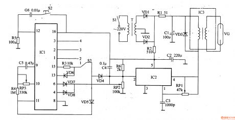
The ozone sterilizer circuit consists of Power circuit, timing control circuit and high-voltage circuit (showed in picture 9-100).
The 220V AC voltage will produce 12V DC voltage after bunched by T and rectified by VD1 and VD2. When it is not the right time VD4 and VD5 is off due to the low positive terminal. Oscillator which consists of IC2, RP1 and C3 works and generates l5kHz oscillation signal. It produces pulsed high voltage by boost module IC3 and the ozone is produced by ozone tube. When the regular time ends the high voltage on VG disappears. (View)
View full Circuit Diagram | Comments | Reading(1318)
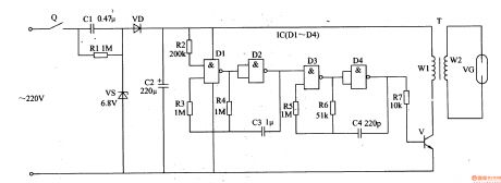
Ozone Sterilizer (the 2nd)
Published:2011/5/19 8:14:00 Author:Felicity | Keyword: Ozone Sterilizer (the 2nd)
Work of the Ozone Sterilizer Circuit
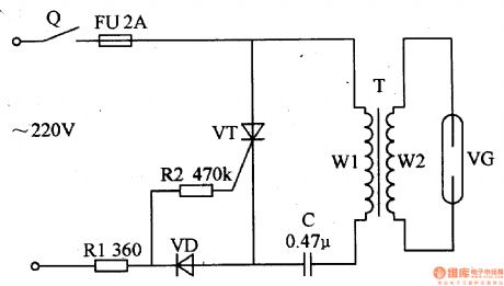
When we turn on the timer Q the 220V AC voltage is limited and bucked by R1 and separate into two parts. One is supplied to VT's gate through R2 while the other one is supplied between VT's anode and cathode and makes VT conducted in AC's positive half cycle and stopped in AC's negative half cycle. With the intermittent work of VT and C step-up transformer T's winding W2 will produce pulse high voltage. Put this voltage on VG to make it produce ozone. (View)
View full Circuit Diagram | Comments | Reading(624)
Ozone Sterilizer (the 1st)
Published:2011/5/30 6:13:00 Author:Felicity | Keyword: Ozone Sterilizer (the 1st),
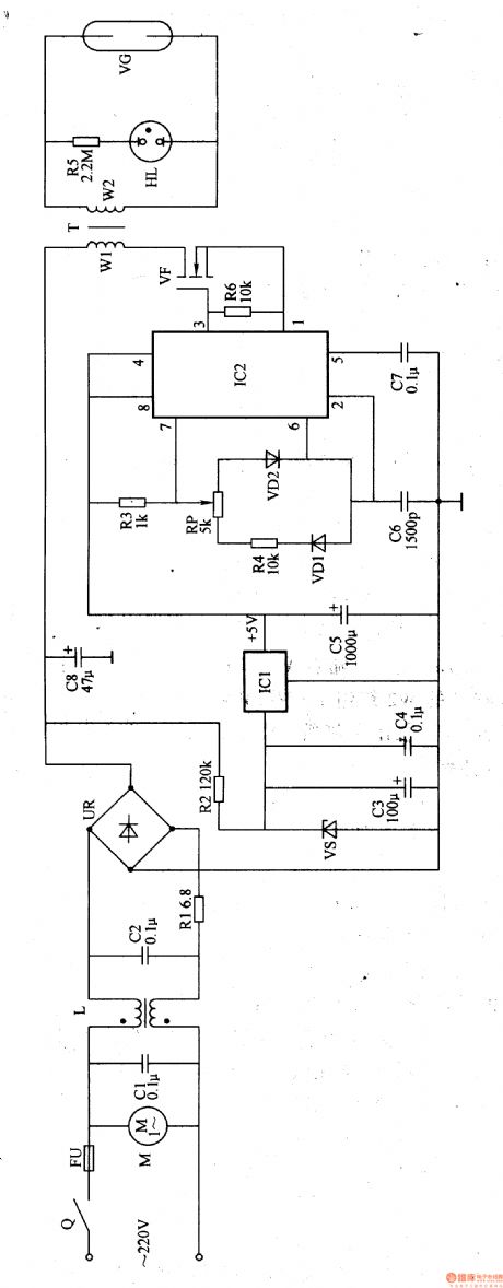
Work of the circuit
The ozone sterilizer circuit consists of Power circuit, oscillator circuit and ozone generator circuit (showed in picture 9-98).Turn on the timer Q and the fan motor starts to work. The 220V AC voltage transforms into 300V DC voltage. The voltage will separate into two parts. One is supplied to ozone production circuit while the other one supplies +5V working voltage to high-frequency generator being bucked, stabilized, filtered and re-stabilized by R2, VS, C3 and ICl. When the high-frequency generator works impulse high voltage is produced. The impulse high voltage is pressed on ozone tube VG. Make VC produce ozone of a certain potency which is eliminate by fan or air pump. Ifthe regular time is over timer Qwill beturned off. Then the power is cut off. (View)
View full Circuit Diagram | Comments | Reading(559)
Disinfectant Manufacturer (the 4th)
Published:2011/5/19 21:13:00 Author:Felicity | Keyword: Disinfectant Manufacturer (the 4th),
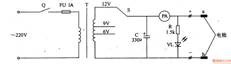
Work of the circuit
The Disinfectant Manufacturer Circuit consists of timer Q, fuse box FU, voltage transit switch S, mains transformer T, filtering fuse box C, ammeter PA, electrical resistor R, diode VL and pole a, b. (It is showed in picture 9-95)
When we use it we should put pole a, b in a container which has salt solution in it and turn on timer Q. 220V AC voltage is separated into two parts after being reduced and filtered by T and C. one is supplied to pole a, b while the other one lightens VL.
When the regular time is over Q is turned off. And it willcut off the power. Then the disinfectant is manufactured. (View)
View full Circuit Diagram | Comments | Reading(412)
M9082(TV) infrared remote control transmitting microprocessor
Published:2011/5/26 8:50:00 Author:Lena | Keyword: infrared, remote control, transmitting, microprocessor
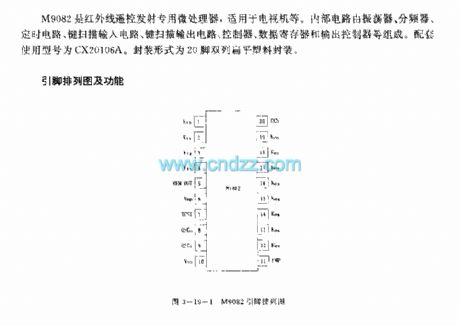
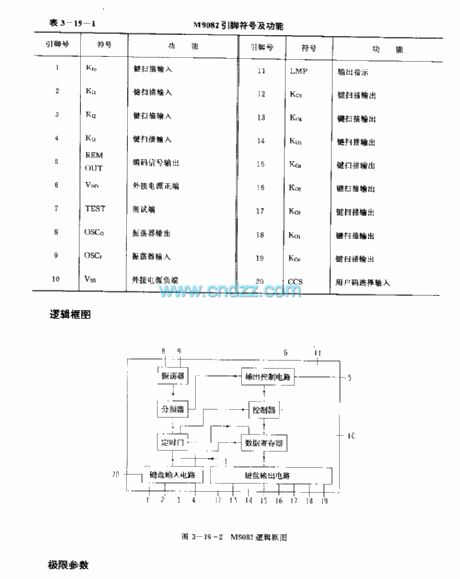

M9082 is an infrared remote control transmitting microprocessor,applied to TVs etc.Internal circuit consists of oscillator, divider, timing circuit, key scan input circuit, key scan output circuit, controller, data register and output controller. Supporting types is CX20106A.Package form is 20 pins dual flat plastic package.
(View)
View full Circuit Diagram | Comments | Reading(451)
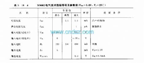
M50163—150SP(TV) infrared remote control receiving microprocessor
Published:2011/6/1 9:36:00 Author:Lena | Keyword: infrared, remote control, receiving microprocessor
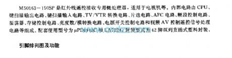
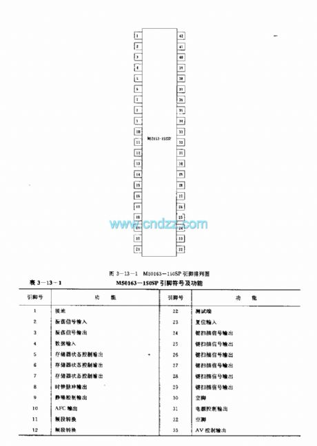
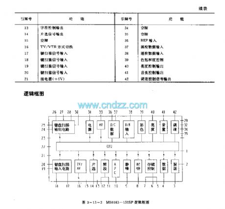
M50163-150SP is an infrared remote control receiving microprocessor which is applied to TV etc. Internal circuit consists of CPU, key scan output circuit, key scan input circuit, TV/VTR converter circuit, chip select circuit, AFC circuit, frequency band control circuit, oscillator, storage control circuit, lightness digital/mimic converter circuit, source switch control circuit and video AV control remote signal processing circuit. Related used type is CX20106A. Package model is 20-pin dual-in-line plastic package.
(View)
View full Circuit Diagram | Comments | Reading(610)
M50462AP (TV) infrared remote control transmitting microprocessor
Published:2011/6/1 9:35:00 Author:Lena | Keyword: infrared, remote control, transmitting, microprocessor

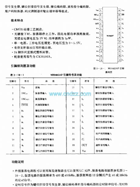
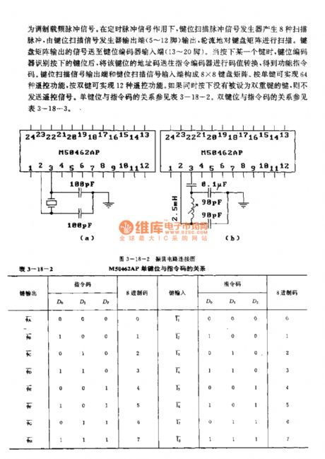
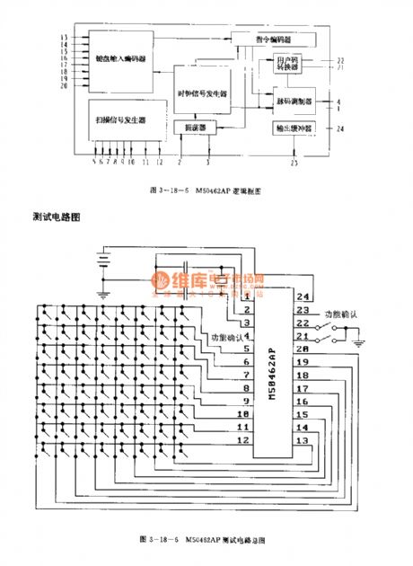
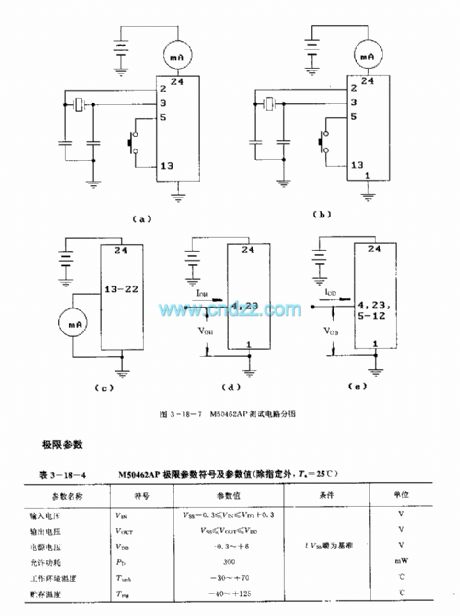
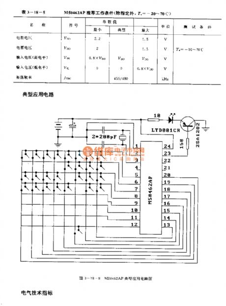
M50462AP is an infrared remote control transmitting microprocessor applied to TV etc. Internal circuit composed by oscillator, clock signal generator, key scan signal generator, key coder, remote control instruction coder, user code converter, code modulator and output buffer etc.
Technology features
Si-gate CMOS ProcessWhen no keyis pressed, the oscillator stop work, so supply power loss is very low. When power supply voltageis 3V, the loss is 3μW.Single power supply, work voltage(2-2.5V) range is wide.
(View)
View full Circuit Diagram | Comments | Reading(653)
Hearing-aid (the 5th)
Published:2011/6/6 5:01:00 Author:Felicity | Keyword: Hearing-aid (the 5th)

Work of the circuit
The hearing-aid circuit consists of amplifying output circuit, volume controlling circuit and voice-frequency amplifying circuit. (It is showed in picture 9-81.).
Turn on the switch S and the machine begins to work. BM turns the sound signal it collects into electric signal. Then the electrical signal drives BE to make sound . Some of IC’s outputting signals can adjust IC’s inputting and outputting voltage after being filtered by C5, RP, VD and C3. In this way the volume can be controlled automatically.
If you change the value of RP you can change the volume. (View)
View full Circuit Diagram | Comments | Reading(4328)
Hearing-aid (the 4th)
Published:2011/6/6 5:07:00 Author:Felicity | Keyword: Hearing-aid (the 4th)
Work of the circuit
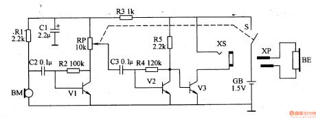
The hearing-aid circuit consists of power circuit, volume amplifier circuit and amplifying output circuit. (It is showed in picture 9-80.).
Turn on the switch S and GB supplied 1,5V voltage to the circuit. BM turns the sound signal it collects into electric signal which drives BE to make sound after being adjusted by V1,V2 and V3.
If you change the value of RP you can change the volume. (View)
View full Circuit Diagram | Comments | Reading(2608)
| Pages:165/195 At 20161162163164165166167168169170171172173174175176177178179180Under 20 |
Circuit Categories
power supply circuit
Amplifier Circuit
Basic Circuit
LED and Light Circuit
Sensor Circuit
Signal Processing
Electrical Equipment Circuit
Control Circuit
Remote Control Circuit
A/D-D/A Converter Circuit
Audio Circuit
Measuring and Test Circuit
Communication Circuit
Computer-Related Circuit
555 Circuit
Automotive Circuit
Repairing Circuit