Signal Processing
Ozone Sterilizer (the 3th)
Published:2011/5/19 8:12:00 Author:Felicity | Keyword: Ozone Sterilizer (the 3th), | From:SeekIC

Work of the Ozone Sterilizer Circuit
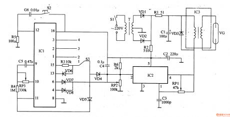
The ozone sterilizer circuit consists of Power circuit, timing control circuit and high-voltage circuit (showed in picture 9-100).
The 220V AC voltage will produce 12V DC voltage after bunched by T and rectified by VD1 and VD2. When it is not the right time VD4 and VD5 is off due to the low positive terminal. Oscillator which consists of IC2, RP1 and C3 works and generates l5kHz oscillation signal. It produces pulsed high voltage by boost module IC3 and the ozone is produced by ozone tube. When the regular time ends the high voltage on VG disappears.
Reprinted Url Of This Article:
http://www.seekic.com/circuit_diagram/Signal_Processing/Ozone_Sterilizer_the_3th.html
Print this Page | Comments | Reading(3)

Article Categories
power supply circuit
Amplifier Circuit
Basic Circuit
LED and Light Circuit
Sensor Circuit
Signal Processing
Electrical Equipment Circuit
Control Circuit
Remote Control Circuit
A/D-D/A Converter Circuit
Audio Circuit
Measuring and Test Circuit
Communication Circuit
Computer-Related Circuit
555 Circuit
Automotive Circuit
Repairing Circuit
Code: