Signal Processing
Ozone sterilizer (the 8th)
Published:2011/5/19 8:01:00 Author:Felicity | Keyword: Ozone sterilizer, | From:SeekIC

Work of the circuit
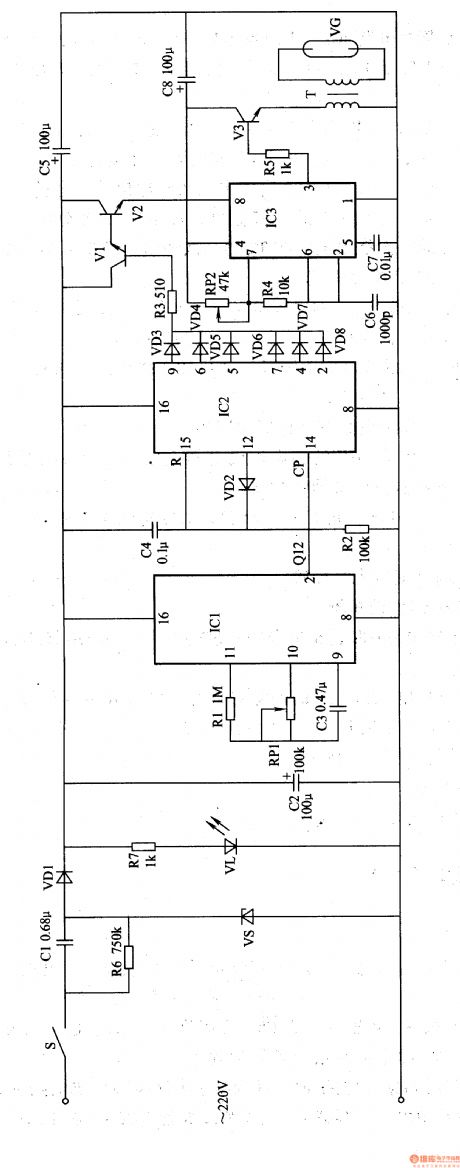
The ozone sterilizer circuit consists of power circuit, timing control circuit, and the ozone generator circuit (showed in picture 9-105).
When we Turn the power switch S the 220V cross voltage is bucked, regulated, rectified and filtered by C8,VS,VDl and CI. And then it produces +l2V voltage. It turns into two parts. One supplies the timing control circuit while the other one lightens VL after being bucked and limited by R7.
The Oscillation signal generated by ICL Internal Oscillator (which consisters of ICL,RL,RPL and C3) is outputed prom pin 2 through internal divider. Then make it Intermittently conducted between V1 and V2. In that way the ozone generator circuit intermittently gets power and works.
Reprinted Url Of This Article:
http://www.seekic.com/circuit_diagram/Signal_Processing/Ozone_sterilizer_(the_8th).html
Print this Page | Comments | Reading(3)

Article Categories
power supply circuit
Amplifier Circuit
Basic Circuit
LED and Light Circuit
Sensor Circuit
Signal Processing
Electrical Equipment Circuit
Control Circuit
Remote Control Circuit
A/D-D/A Converter Circuit
Audio Circuit
Measuring and Test Circuit
Communication Circuit
Computer-Related Circuit
555 Circuit
Automotive Circuit
Repairing Circuit
Code: