Signal Processing
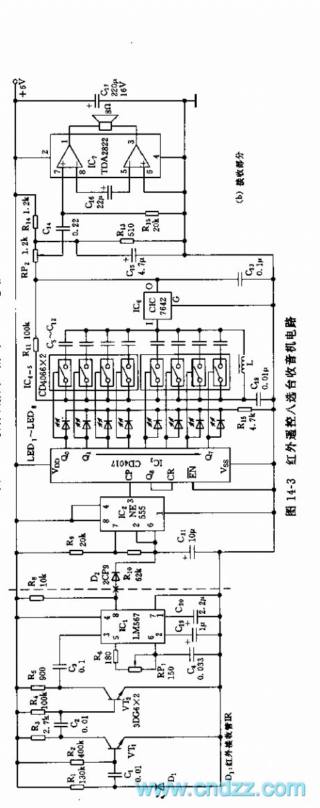
555 infrared remote control eight-channel selection radio circuit
Published:2011/6/14 8:18:00 Author:TaoXi | Keyword: 555, infrared remote control, eight-channel selection, radio | From:SeekIC

As the figure 14-3 shows, the infrared remote control eight channels radio circuit is composed of the infrared remote control transmitter, the remote control decoder and the channel selection recording part.The remote transmitter is composed of the multivibrator (composed of the 555 and R1, RP1, C1) and the infrared transmitting tube, the oscillation frequency f=1.44/(R1+RP1)C1, the frequency of the figure parameters is about 120kHz, the duty ratio is 67%.
The receiving part is composed of the infrared receiving amplifier, the decoding circuit IC1, the pulse distribution circuit, the electronic switch selective passing radio circuit and the amplifier stage. D1 is the receiving tube which can be used with the launch infrared diode, the VT1 and VT2 are the signal amplification stage. The IC1 uses the PLL audio decoder LM567.
The monostable trigger circuit is composed of the IC2(555) and R9, R10, C21, this circuit outputs the pulse with 1 second pulse width.
Reprinted Url Of This Article:
http://www.seekic.com/circuit_diagram/Signal_Processing/555_infrared_remote_control_eight_channel_selection_radio_circuit.html
Print this Page | Comments | Reading(3)

Article Categories
power supply circuit
Amplifier Circuit
Basic Circuit
LED and Light Circuit
Sensor Circuit
Signal Processing
Electrical Equipment Circuit
Control Circuit
Remote Control Circuit
A/D-D/A Converter Circuit
Audio Circuit
Measuring and Test Circuit
Communication Circuit
Computer-Related Circuit
555 Circuit
Automotive Circuit
Repairing Circuit
Code: