
Signal Processing
Index 172
12-nary counter circuit
Published:2011/6/5 10:16:00 Author:John | Keyword: 12-nary counter
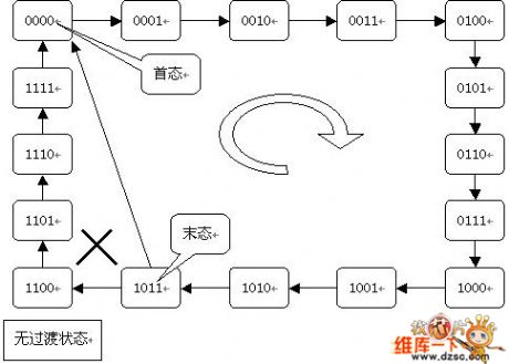
In the integrated counter with synchronous resetting performance, reset method (synchronous reset method) is used. It is different from the integrated counter with asynchronous reset function. The reset method used is called asynchronous reset method. This is determined by the difference on the actions of a synchronous reset and asynchronous reset function. According to synchronous reset function, when the reset terminal is active and is not able to immediately reset, the CP valid edge must be triggered for reset. Therefore, N-nary counter composed of the integrated counter with synchronous reset function does not have the transition state.
(View)
View full Circuit Diagram | Comments | Reading(406)
256-nary counter circuit
Published:2011/6/5 10:39:00 Author:John | Keyword: 256-nary counter
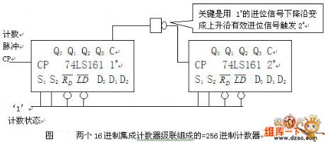
In the 160-counter, when S1 = S2 = 0, the counter to keep Q, C = 0. When S1 = S2 = 1, the counter starts to count.
A.Define 1# a low chip and define #2 a high chip.
Use a low chip’s injection output end C as the control signal, which is carried to a high chip (C edge is used to control S1 and S2 ends of high chip rather than to trigger the CP pulse end of a high counter. The value of high counter can be controlled or kept. When the low counter counts from state 0 to 8, the C is equal to zero. The counting value of high counter S1 = S2 = 0 is got. And high counter has not been compared.
(View)
View full Circuit Diagram | Comments | Reading(413)
VCO circuit
Published:2011/6/4 10:17:00 Author:John | Keyword: VCO
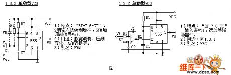
There are many monostable type VCO, which are all rather complex. For simplicity, we just divide it into 2 different units. The circuit without any auxiliary devices is 1.3.1. The circuit using transistors, operational amplifier and other auxiliary devices is 1.3.2. 2 common used circuits are shown in the figure.
1) Features: RT-7.6-CT , the end 2 is input with modulated pulse and the end 5 is set by modulated signal Vct 5.
2) Functions: modulation of pulse width, change of voltage-frequency, A / D change
3) Alias: PWM
(View)
View full Circuit Diagram | Comments | Reading(615)
Five-divider frequency circuit
Published:2011/6/5 2:52:00 Author:John | Keyword: Five-divider frequency
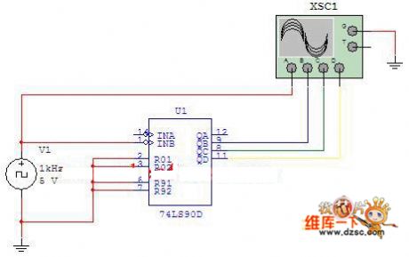
Figure: Five-divider frequency circuitWhen the counting pulse is input from the INB, the output would be QB, QC and QD. Such would form quinary counter (also called five-divider frequency circuit), whose circuit is just as shown in Figure 2-3. Use four-trace oscilloscope to record the output waveform. (View)
View full Circuit Diagram | Comments | Reading(446)
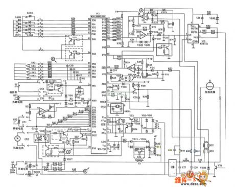
pic16c54 control Gree electronic sterilizer circuit
Published:2011/6/4 13:29:00 Author:John | Keyword: electronic sterilizer

pic16c54 control Gree electronic sterilizer circuit is shown in the following.
(View)
View full Circuit Diagram | Comments | Reading(1613)
Symmetric multivibrator circuit
Published:2011/6/4 23:59:00 Author:John | Keyword: Symmetric multivibrator
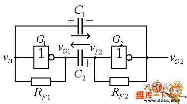
Figure: Symmetric multivibrator circuitMultivibrator is a self-oscillation circuit. Because there is no stable working state, multivibrator is also known as non-steady-state circuit. Specifically, if the multivibrator is at the state 0 at the very beginning, it would keep the state 0 for a period of time and then automatically run into state 1afterwards. If it remains state 1 for a period of time, it will automatically transfer to state 0. Such transfer would occur again and again, outputting the rectangular wave. (View)
View full Circuit Diagram | Comments | Reading(564)
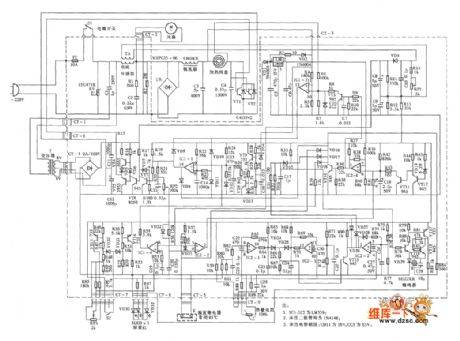
HF-10A type electromagnetic cooker circuit
Published:2011/6/5 22:12:00 Author:John | Keyword: electromagnetic cooker

HF-10A type electromagnetic cooker circuit is shown in the following.
(View)
View full Circuit Diagram | Comments | Reading(855)
Yonghua M0-88 type electromagnetic cooker circuit
Published:2011/6/5 22:08:00 Author:John | Keyword: electromagnetic cooker

Yonghua M0-88 type electromagnetic cooker circuit is shown below.
(View)
View full Circuit Diagram | Comments | Reading(679)
Wanbao DC2-13 series type electromagnetic cooker circuit
Published:2011/6/5 10:45:00 Author:John | Keyword: electromagnetic cooker

Wanbao DC2-13 series type electromagnetic cooker circuit is shown in the following.
(View)
View full Circuit Diagram | Comments | Reading(960)
Suopu SP-200 type cooker circuit
Published:2011/6/5 10:20:00 Author:John | Keyword: cooker

Suopu SP-200 type cooker circuit is shown below.
(View)
View full Circuit Diagram | Comments | Reading(769)
Fujitsu computer-style electromagnetic cooker circuit (1H ~ 1000H (700 ~ 1300W)
Published:2011/6/6 0:38:00 Author:John | Keyword: electromagnetic cooker

Fujitsu computer-style electromagnetic cooker circuit (1H ~ 1000H (700 ~ 1300W) is shown in the following.
(View)
View full Circuit Diagram | Comments | Reading(751)
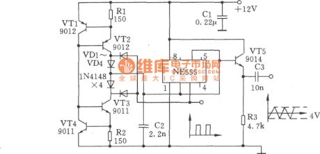
Triangular Wave and Square-wave Generator Circuit Composed of NE555
Published:2011/6/4 10:08:00 Author:Joyce | Keyword: Triangular Wave , Square-wave , Generator, NE555
(View)
View full Circuit Diagram | Comments | Reading(665)
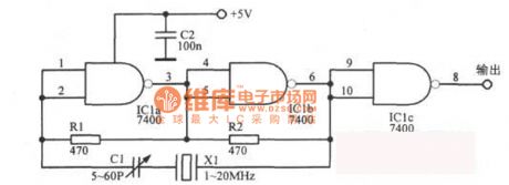
NAND TTL Crystal Oscillator Circuit
Published:2011/5/29 1:38:00 Author:Joyce | Keyword: NAND , TTL , Crystal Oscillator
View full Circuit Diagram | Comments | Reading(1615)
12kHz Intermediate-frequency Oscillator Circuit
Published:2011/6/2 3:49:00 Author:Joyce | Keyword: 12kHz, Intermediate-frequency , Oscillator
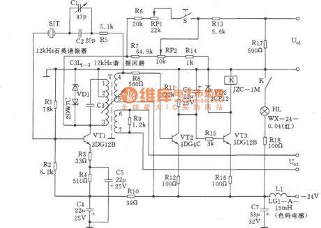
The 12kHz intermediate frequency oscillators in the graph is composed of 12kHz quartz oscillators, output level adjustment,a level ascending circuit and a alarm circuit. It uses a new single tube tuning transformer feedback oscillator circuit. In the feedback circuit, 12 kHz quartz crystal resonators are connected in series, thus the oscillation frequency depends on the performance of the l2kHz quartz crystal resonators .With regard to improving the reliability of oscillators and stability of the output, it uses AC circuit with fixed amplitude. In other respects, this circuit makes use of components with stable performance, and tries to simplify the circuit, thus ensuring good performance. (View)
View full Circuit Diagram | Comments | Reading(779)
300kHz Signal Generator Circuit
Published:2011/6/4 9:39:00 Author:Joyce | Keyword: 300kHz , Signal Generator
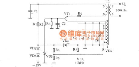
As shown in the figure is a 300 kHz signal generator. The voltage-controlled oscillator consists of VT1,T1, VD4 and other relevant components, with LC collector tuning.VT1 is the oscillating tube, while variode VD4, capacitance C3 ~ C6 and inductance of transformer T1`s windings 1 ~ 3 compose a tuned circuit. The variode VD4 works as control voltage is sent to its negative terminal to change its electric capacity. Oscillating signal is output by windings 6 ~ 7 of T1. Among them, C6 is a frequency trim capacitance. VD3 is to stabilize the working voltage of oscillator stage, and the stabilized voltage is 6.8 V ± 0.2 V. (View)
View full Circuit Diagram | Comments | Reading(715)
Atlantis electromagnetic cooker circuit
Published:2011/6/5 22:11:00 Author:John | Keyword: electromagnetic cooker
Atlantis electromagnetic cooker circuit is shown in the following.
(View)
View full Circuit Diagram | Comments | Reading(1073)
Panasonic induction cooker circuit (KY-P2N)
Published:2011/6/6 23:41:00 Author:John | Keyword: induction cooker
Panasonic induction cooker circuit (KY-P2N) is shown below.
(View)
View full Circuit Diagram | Comments | Reading(1663)
6-nary counter( achieved by T4290 setting method)
Published:2011/6/5 9:38:00 Author:John | Keyword: 6-nary counter
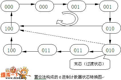
Referring to this problem, first of all, the concept of the counter should be extended. It is not necessary to start counting from state 0. It can start from any state (initial value) and experience N valid count state. Then it would count back to the initial value to form a count cycle. Such is also available to constitute the N nary counter. With setting method, N nary counter starts from the set value and is in the original count cycle. When set side is invalid, it cycles according to the original counting order. When set side is effective, original counting order is forced to disconnect. It comes back to the initial value (set value) for re-starting the next counting cycle. (View)
View full Circuit Diagram | Comments | Reading(393)
10-nary three-yard subtraction counter circuit
Published:2011/6/5 9:55:00 Author:John | Keyword: subtraction counter
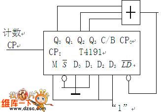
Connection: power supply VCC, ground GND; Enable effective function and M=1 subtraction counter; Connect output terminal to control preset number control terminal (LD), just as shown in Figure 1.
10-nary three-yard subtraction counter circuit (Asynchronous preset number)
Therefore during the basic method, the achieving method is the same regardless of the addition or subtraction counter. But it should be noted that it is necessary to draw the right state transition circuit for the design. And it is necessary to distinguish the circuit wirings of M = 0 (addition) and M = 1 (subtraction). (View)
View full Circuit Diagram | Comments | Reading(443)
digital clock principle box circuit
Published:2011/6/5 4:32:00 Author:John | Keyword: digital clock, principle box

Digital clock system1. Digital clock constitutes: oscillator, divider, counter, decoder, display and other parts 2. The hours, minutes and seconds of the digital clock actually consist of 24 nary counter (00 - 23) and two 60 nary cascaded counters (00-59). 3. Design of a 60 nary counter4. Design of a 24nary counter5. Design of a cascaded counter
Figure: digital clock principle box circuit (View)
View full Circuit Diagram | Comments | Reading(895)
| Pages:172/195 At 20161162163164165166167168169170171172173174175176177178179180Under 20 |
Circuit Categories
power supply circuit
Amplifier Circuit
Basic Circuit
LED and Light Circuit
Sensor Circuit
Signal Processing
Electrical Equipment Circuit
Control Circuit
Remote Control Circuit
A/D-D/A Converter Circuit
Audio Circuit
Measuring and Test Circuit
Communication Circuit
Computer-Related Circuit
555 Circuit
Automotive Circuit
Repairing Circuit