Signal Processing
Five-divider frequency circuit
Published:2011/6/5 2:52:00 Author:John | Keyword: Five-divider frequency | From:SeekIC

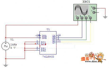
Figure: Five-divider frequency circuitWhen the counting pulse is input from the INB, the output would be QB, QC and QD. Such would form quinary counter (also called five-divider frequency circuit), whose circuit is just as shown in Figure 2-3. Use four-trace oscilloscope to record the output waveform.
Reprinted Url Of This Article:
http://www.seekic.com/circuit_diagram/Signal_Processing/Five_divider_frequency_circuit.html
Print this Page | Comments | Reading(3)

Article Categories
power supply circuit
Amplifier Circuit
Basic Circuit
LED and Light Circuit
Sensor Circuit
Signal Processing
Electrical Equipment Circuit
Control Circuit
Remote Control Circuit
A/D-D/A Converter Circuit
Audio Circuit
Measuring and Test Circuit
Communication Circuit
Computer-Related Circuit
555 Circuit
Automotive Circuit
Repairing Circuit
Code: