
Signal Processing
Index 173
45 nary counter circuit
Published:2011/6/5 4:23:00 Author:John | Keyword: 45 nary counter
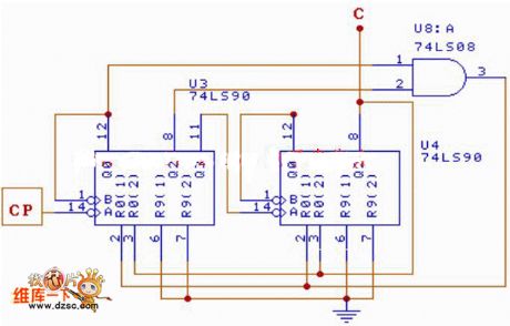
45 nary counter circuit is shown below.
(View)
View full Circuit Diagram | Comments | Reading(390)
The over voltage, low voltage and off-delay operation protection circuit of 555 fridge
Published:2011/5/27 1:11:00 Author:Borg | Keyword: over voltage, low voltage, off-delay operation, protection circuit
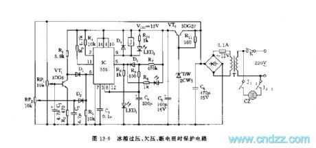
See as Figure 13-9, this is a over voltage and low voltage sampling circuit consisting of RP1,VT1 and RP2,C2MD2, etc, 1/2 of which is the over or low voltage trigger circuit; and the other 1/2 is the time delay circuit, the delaying time is td=1.1R7C4, which is about 6min. The output is controlled by the relay control circuit, the the off-delay operation is over, the 9-lead outputs a low LEV, and J pulls in, J2-2 and J1-1 closes, and the outlet CZ gets power, then the fridge is working.
Figure 13-9 The over voltage, low voltage and off-delay operation protection circuit ofthe fridge (View)
View full Circuit Diagram | Comments | Reading(1976)
The simple washing machine timer circuit of 555 fridge
Published:2011/5/27 1:23:00 Author:Borg | Keyword: washing machine, timer circuit

See as Figure 13-19, the washing machine timer is a single steady timing circuit, which is under the control of the state of water level switch. The single steady time isTd=1.1[(R1~R5)+2R6]CThe time can be changed by the programmed timing switch.
Figure 13-19 The simple washing machine timer circuit ofthe fridge (View)
View full Circuit Diagram | Comments | Reading(2234)
The protector circuit of the 555 multiple functional fridge
Published:2011/5/27 19:36:00 Author:Borg | Keyword: protector circuit, multiple functional fridge
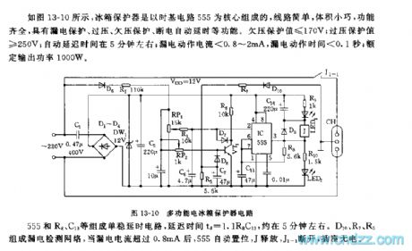
See as Figure 13-10, the fridge protector is formed on the basis of time-base circuits, whose wiring is simple, size is small and functions are complete, and the circuit has functions of leakage protection, over voltage protection, low voltage protection and power failure time delay, etc. The value of low voltage protection is ≤170V; the value of over voltage protection is ≥250V; the auto time delay is about 5min; leakage reacting current is <0.8~2mA, the reacting time is< 0.1S; and the rated output power is 1000W.
555,R8,C13 and so on forms a single steady time delay circuit, the delaying time is td=1.1R8C13, which is about 5min. (View)
View full Circuit Diagram | Comments | Reading(796)
The timing ventilation circuit of 555 auto temperature control
Published:2011/5/27 20:32:00 Author:Borg | Keyword: ventilation circuit, auto temperature control
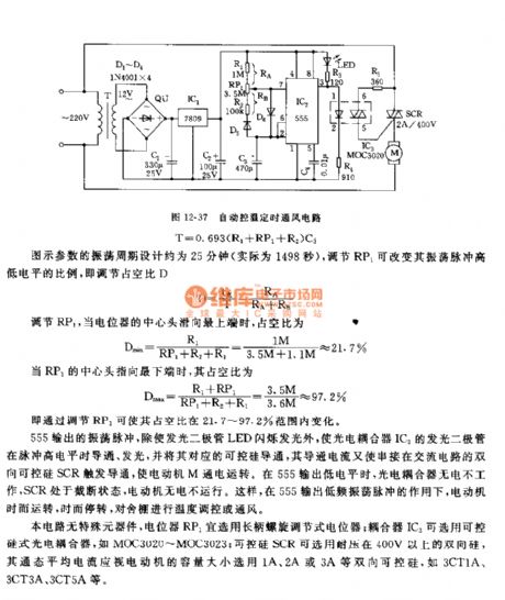
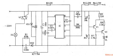
The temperature control ventilation circuit consists of step-down rectifier circuit, long period multi-resonate oscillator, photocoupler and controllable silicon control circuit, etc, which is simple and stable. The circuit can be used to ventilate and cool poultry houses, animal shelters and warm houses,etc. The circuit is as shown in Figure 12-37. The rectifier circuit consists of step-down transformer T, full bridge rectifier QU and C1, etc, the rectified voltage of about 14V is stabilized by the 3-terminal voltage stabilizer LM7809, and it reduces to be a +9V voltage as the working voltage of the backward-stage circuit.
(View)
View full Circuit Diagram | Comments | Reading(694)
The 555 DC raising pressure circuit
Published:2011/6/3 2:15:00 Author:nelly | Keyword: DC, raising pressure
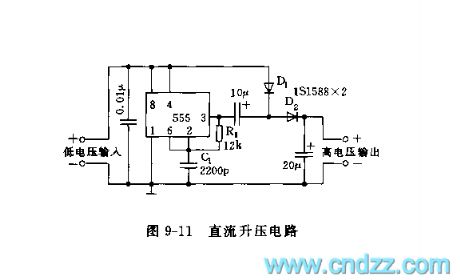
As shown on the figure 9-11, the astable multi-oscillation consists of the 555,R1 and C1. The oscillation frequency depends on the time constant of R1 and C1. The frequency shown on the figure is about 20kHz. The output voltage is about 2.2 times higher than the input DC voltage by dual voltage rectified. The load current can reach 50mA. It uses the bipolar 555. (View)
View full Circuit Diagram | Comments | Reading(594)
The protector circuit of 555 full auto fridge
Published:2011/5/27 1:40:00 Author:Borg | Keyword: protector circuit
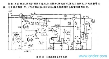
IC1(555),R1~R3,RP1,RP2 ,VT1 and so on consist a over/low voltage circuit. In the voltage range of 170V~240V, the 2-lead of IC1 is in a low voltage, which offsets 555, the output terminal of 3-lead is in a high LEV. Across D3 and R7, the LEV is imposed on VT2 base electrode, and it cooperates with the time delay circuit so that VT2 saturates and becomes conducting, J pulls in and Ja-d are getting through, then the outlet gets power. When the voltage is under 170V or over 240V, the 2-lead of 555 is in a high LEV, and the circuit is reset, the 3-lead is in a low LEV. The time delay circuit consist of VT3,VT4,R8,C4 and so on. (View)
View full Circuit Diagram | Comments | Reading(574)
The fixed cycle pulse generator circuit with the adjustable duty ratio
Published:2011/5/25 6:15:00 Author:Christina | Keyword: fixed cycle, pulse generator, adjustable, duty ratio
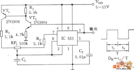
As the figure shows, the astable multivibrator is composed of the 555, VT1, VT2, R1, R2, RP1 and C1. In this figure, the capacitor C1 has the independent charging and discharging circuit, when you adjust RP1, you can change the charging and discharging time constants, but can not change the oscillation frequency. Before C1 is charged to the 2/3VDD threshold electrical level, pin-3 has the high electrical level, that means during the time of t1, VT2 conducts, VT1 fully conducts, so VT1 has the small impedance. By adjusting RP1, you can change the duty ratio between 2% to 98%, the period can not be changed.
(View)
View full Circuit Diagram | Comments | Reading(889)
Radio launch alarm crystal oscillation frequency stabilizing FM circuit
Published:2011/5/25 18:54:00 Author:Christina | Keyword: Radio launch, alarm, crystal oscillation, frequency stabilizing, FM circuit
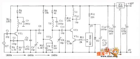
The crystal oscillation frequency stabilizing FM circuit is as the figure shown, this circuit can be used in the radio launch alarm. So it has the features of simple to use, stable performance, small size, low cost, it is one kind of high cost-effective circuit.
Performance indexes:
Operating frequency: 85 to 120MHz;
output power: 5~200mW(adjustable);
Launch distance: 50~1000m;
operating voltage: 9VDC;
operating current: 50 to 60 mA.
The transistors VTl and VT2 use the 3DGl30C、β≥50, the VT3 uses the L413K amplifier tube, the VT4 is 8050、β≥80. The voltage stabilization diode VD uses the 3V, 0.5W voltage stabilization tube. ICl is the KD-9561 simulation soft package sound integrated circuit. All the high-frequency circuit oscillation capacitances uses the high frequency ceramic or the polyester capacitor.
(View)
View full Circuit Diagram | Comments | Reading(496)
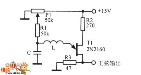
50kHz Sine wave oscillator circuit diagram
Published:2011/6/1 6:41:00 Author:Lucas | Keyword: 50kHz, Sine wave , oscillator
View full Circuit Diagram | Comments | Reading(810)
TOSHIBA F3SS color TV movement protection circuit
Published:2011/5/26 21:02:00 Author:Christina | Keyword: TOSHIBA, color TV, movement, protection circuit
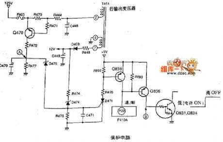
1.+B line over-current protection circuit
When the +B line is over-current, the current of R470 increases, the pressure drop of R470 increases. When the pressure drop of R470 makes the e electrode's voltage higher than b electrode (0.7V), the Q470 conducts.
2.+B over-voltage protection circuit
When the +B line is over-voltage, the pulse voltage which is output by the line output transformer is rectified by D408, then is filtered by C449.
3.Field output over-current protection circuit
When the output current is over-current, the pin-6's voltage of the supply field output integrated circuit Q301 reduces, the pressure drop of resistance R490 increases, the Q490 conducts, the D490 conducts, the D471 conducts, the Q838 conducts. (View)
View full Circuit Diagram | Comments | Reading(838)
555 thermos touch automatic drain circuit
Published:2011/6/1 1:51:00 Author:TaoXi | Keyword: 555, thermos, touch, automatic drain
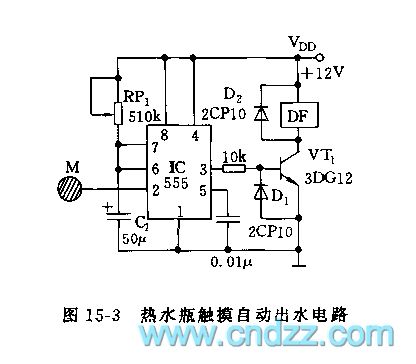
As the figure 15-3 shows, this circuit uses the 555 as the core to form the monostable trigger device. When the hand touchs the sequin M, the thermos will drain automaticly.
The monostable timing circuit is composed of the 555 and RP1,C1, the timing time td=1.1RP1C1, by adjusting RP1, you can change the drain time, the longest drain time is 10s. You should adjust it before using. The VT1 can be used to drive the electromagnetic valve DF's amplifier, the VT1 will conduct in the timing time, so the coil of the electromagnetic valve gets power, the valve rod moves down under the effect of the magnetic force to increase the horizontal pressure, then the hot water gets out from the water outlet.
(View)
View full Circuit Diagram | Comments | Reading(1059)
555 automatic AC voltage stabilizer circuit
Published:2011/6/1 2:20:00 Author:TaoXi | Keyword: 555, automatic, AC, voltage stabilizer

As the figure 15-9 shows, the voltage stabilizer circuit is composed of the voltage stabilizer part and protection part. When the input AC voltage is in the range of 160V~250V, the output voltage will be 220+/-10%, when the output voltage is more than 250V, the circuit will cut off the load automaticly; when the outage happens, the protector will automatic delay about six minutes, then turns on the power.
The two same composite amplifier is composed of the VT1, VT2, VT3, VT4 and some capacitance resistance elements. Their input signals were taken from the different contacts of the self-coupling transformer, after the rectification and pressure separate, they add to the base electrodes of the VT1 and VT3. When the input voltage is lower than 190V, the J1, J2 are not action.
(View)
View full Circuit Diagram | Comments | Reading(5214)
555 disabled person three-purpose electronic circuit
Published:2011/5/25 4:05:00 Author:TaoXi | Keyword: 555, disabled person, three-purpose, electronic circuit
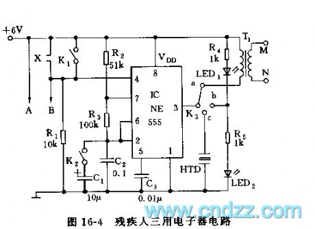
As the figure 16-4 shows, the three-purpose electronic circuit uses the 555 as the core, it has the following functions:
Wake-up function: X connects to the electronic alarm clock chip, in peacetime X is the opening circuit, K3 is in the position of contact point a. When the timing time is up, X adds the voltage to pin-4, so 555 starts working, the oscillation frequency f1=1.44/(R2+2R3)C2.
Eyesight exercise: if you close K1 and K2, then move K3 to the b contact point, so 555 forms the multivibrator which has the frequency of 1Hz, the figure parameter's oscillation frequency is about 1Hz.
The blind man water detection alarm: if you disconnect K1 and K2, and move K3 to the C port, then install A, B at the bottom of the cane, when you are working, if the bottom of the cane contacts the water, pin-4 has the high electric potential to make 555 in the oscillation state.
(View)
View full Circuit Diagram | Comments | Reading(646)
555 shock vibration alarm circuit
Published:2011/5/30 9:48:00 Author:TaoXi | Keyword: 555, shock vibration, alarm
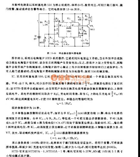
This alarm circuit uses the double time base circuit 556 as the core, it has some points of features: small size, pure report sound, and it can be used in wide range of applications such as the knocking door alarm, the breaking door alarm, the vibration or shock warning. The circuit is as shown in figure 15-44.
The IC1 uses the double time base circuit 556, the monostable trigger timing circuit is composed of it's left part IC1-a(1/2 556) and R3, C1. In peacetime, the partial pressure effect makes the trigger port pin-6's electric potential higher than 1/3VDD, and this trigger circuit is in the reset state. When HTD is impacted or oscillated, the exchange piezoelectric signal which is produced by the deformation will make the trigger to flip and set, pin-3 has the high electrical level.
(View)
View full Circuit Diagram | Comments | Reading(1072)
555 simple practical earthquake alarm circuit
Published:2011/5/30 21:08:00 Author:TaoXi | Keyword: 555, simple, practical, earthquake, alarm circuit
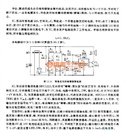
The earthquake alarm circuit is composed of the shock vibration sensor, the monostable timing circuit and the voice alarm circuit.etc, as the figure 15-51 shows. This circuit has the function of sound & light alarm to the earthquake which is more than 4 class in the medium or short distance.
The IC1 uses the time base circuit 555, the monostable trigger timing circuit is composed of the 555 and the R2,C1. In peace time, the pin-2 has the high electric potential to make the 555 in the reset state. If the earthquake happens, the hammer touches with the outer phase, pin-2's low electric potential makes the 555 in the set state,pin-3 outputs the high electric potential to supply the power to IC2 voice generating circuit. The monostable temporary stabilization time td=1.1R2C1.
(View)
View full Circuit Diagram | Comments | Reading(1700)
555 electronic language model reception circuit
Published:2011/6/1 18:49:00 Author:TaoXi | Keyword: 555, electronic, language, model, reception circuit
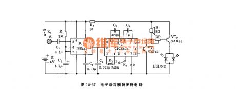
As the figure 15-37 shows, the circuit is composed of the monostable trigger and the language integrated audio circuit, and this circuit can be used in the shop and restaurant.etc.
The monostable trigger is composed of the 555 and R1, C2, when the guest touches the sequin A, the 555 circuit sets, pin-3 has the high electrical level to trigger IC2. IC2 is the language integrated circuit ICI5603 (or NS268.etc.), if pin-2 has the trigger electrical level signal, the internal memory starts working and sends out the voice of you are welcome through the speaker. At the same time the two LEDs turn on. When the 555 temporary state is finished, pin-3 has the low electrical level, the circuit is in quiet.
(View)
View full Circuit Diagram | Comments | Reading(479)
Car Windshield Wiper Controller (the 3rd)
Published:2011/5/20 2:55:00 Author:Felicity | Keyword: Car Windshield Wiper Controller (the 3rd)

Work of the circuit
The circuit consists of examining circuit, Multivibrator and motor control circuit (It is showed in the picture 7-165.).
When it is rainy the Multivibrator begins to work. When the outputted signal is of high level the windshield wiper begins to work. And when the signal is of low level the motor stops working.
When the rain is not heavy the motor will just wok for a short time. And when the rain is heavy the motor will work for a rather long time. (View)
View full Circuit Diagram | Comments | Reading(1031)
Eye-care Lamps (the 1st)
Published:2011/5/20 1:49:00 Author:Felicity | Keyword: Eye-care Lamps (the 1st)
Work of the circuit
The circuit consists of power circuit, touching light adjust circuit, control execute circuit and light examine circuit (It is showed in picture 9-68.).
When hand touches pole A body inducted signal is supplied to rC’s pin 5 through resistor R5 and R6 to make circuit within IC work. The function of light examining can protect the user’s vision in case the light is too dim. (View)
View full Circuit Diagram | Comments | Reading(606)
M50431—101SP (TV)infrared remote control receiving microprocessor circuit
Published:2011/5/26 9:58:00 Author:Lena | Keyword: infrared, remote control, receiving, microprocessor
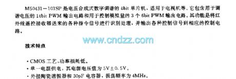
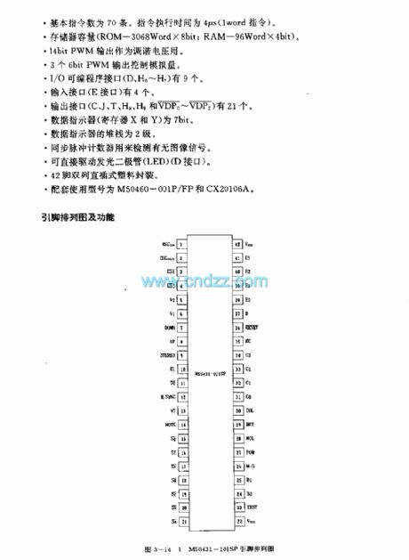
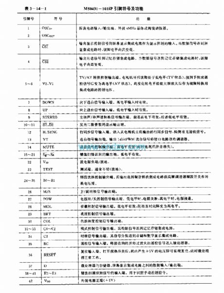
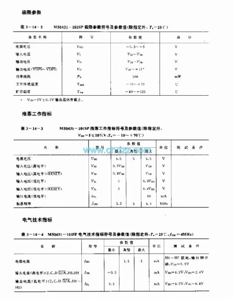
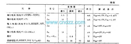
M50431-101SP is a voltage synthesis digital tuning 4-bit singlechip, applied to TV etc. It contains 14bit PWM output circuit used to tune voltage and three 6-bit PWM output circuit used to control analog quantity. The function is identifying different instruction signals sent by infrared remote control receiver, then output control signals to corresponding control circuit.
technology featureCMOS technics, power loss is low.Single power supply, the voltage value is 5V±0.5VConnectting Ceramic Resonator and 30pF capacitor, oscillation frequency is 4MHz.
(View)
View full Circuit Diagram | Comments | Reading(1390)
| Pages:173/195 At 20161162163164165166167168169170171172173174175176177178179180Under 20 |
Circuit Categories
power supply circuit
Amplifier Circuit
Basic Circuit
LED and Light Circuit
Sensor Circuit
Signal Processing
Electrical Equipment Circuit
Control Circuit
Remote Control Circuit
A/D-D/A Converter Circuit
Audio Circuit
Measuring and Test Circuit
Communication Circuit
Computer-Related Circuit
555 Circuit
Automotive Circuit
Repairing Circuit