Signal Processing
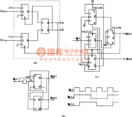
The 3-way frequency circuit of symmetric output(74LS109 and 74LS113)
Published:2011/6/17 20:25:00 Author:Borg | Keyword: 3-way frequency, symmetric output | From:SeekIC

In the figure is the 3-way frequency circuit of symmetric output. Usually, when we use common counter to odd-split the digital pulse, even the input is the symmetric signal, the output won't be the splitting frequency of 50% duty cycle, the reason is that all the internal triggers are motivated by the rising edge (or the dropping edge). To solve the problem, we can use a J and K, two JK triggers that are motivated by the clock, see as figure (a). The circuit includes two JK triggers and a RS trigger.
Reprinted Url Of This Article:
http://www.seekic.com/circuit_diagram/Signal_Processing/The_3_way_frequency_circuit_of_symmetric_output74LS109_and_74LS113.html
Print this Page | Comments | Reading(3)

Article Categories
power supply circuit
Amplifier Circuit
Basic Circuit
LED and Light Circuit
Sensor Circuit
Signal Processing
Electrical Equipment Circuit
Control Circuit
Remote Control Circuit
A/D-D/A Converter Circuit
Audio Circuit
Measuring and Test Circuit
Communication Circuit
Computer-Related Circuit
555 Circuit
Automotive Circuit
Repairing Circuit
Code: