Signal Processing
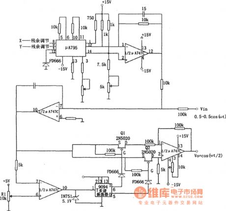
The sine wave frequency-halving circuit (μA747 and μA795)
Published:2011/6/17 20:54:00 Author:Borg | Keyword: sine wave, frequency-halving circuit | From:SeekIC

To an ordinary digital frequency splitting circuit, the weakness is that it can't maintain the former sine waveform. If the sine wave output is needed, we can add a additional filter or the like, see as the circuit. In the circuit, the integrated circuits of μA795 and μA747C compose the standard square root circuit. The output of circuit the positive square root of the input voltage absolute value. When the input ±0.5cosωt, the output is cos( ωt/2). The trigger 9094, analog switches (Q1 and Q2) and half of the computing amplifier μA747 consist of the absolute value removing circuit.
Reprinted Url Of This Article:
http://www.seekic.com/circuit_diagram/Signal_Processing/The_sine_wave_frequency_halving_circuit_μA747_and_μA795.html
Print this Page | Comments | Reading(3)

Article Categories
power supply circuit
Amplifier Circuit
Basic Circuit
LED and Light Circuit
Sensor Circuit
Signal Processing
Electrical Equipment Circuit
Control Circuit
Remote Control Circuit
A/D-D/A Converter Circuit
Audio Circuit
Measuring and Test Circuit
Communication Circuit
Computer-Related Circuit
555 Circuit
Automotive Circuit
Repairing Circuit
Code: