Signal Processing
Ward Caller Two
Published:2011/5/14 6:41:00 Author:Felicity | Keyword: Ward Caller , | From:SeekIC

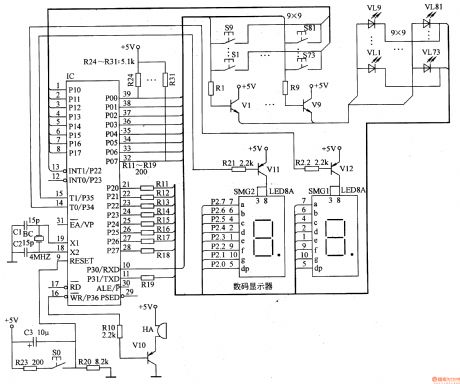
When one button of S1-S81 is pressed, the inside program control circuit of the IC detects the bed number represented by the button number. And the pin 16 is at low level to make V10 close, and HA sends out a call. Pin 15 and pin 14 are at low level to make V11 or V12 close. Pin 21-28 output signals to drive the digital code scope to display the calling bed number while the LED corresponding to the pressed button is on.
Once the reset button S0 is pressed, the lighted LED will be off, and the number displayed on the digital code scope will disappear, and HA will stop.
Reprinted Url Of This Article:
http://www.seekic.com/circuit_diagram/Signal_Processing/Ward_Caller_Two.html
Print this Page | Comments | Reading(3)

Article Categories
power supply circuit
Amplifier Circuit
Basic Circuit
LED and Light Circuit
Sensor Circuit
Signal Processing
Electrical Equipment Circuit
Control Circuit
Remote Control Circuit
A/D-D/A Converter Circuit
Audio Circuit
Measuring and Test Circuit
Communication Circuit
Computer-Related Circuit
555 Circuit
Automotive Circuit
Repairing Circuit
Code: