Signal Processing
The temperature controller circuit of 555 fans
Published:2011/5/29 6:47:00 Author:Borg | Keyword: temperature controller | From:SeekIC

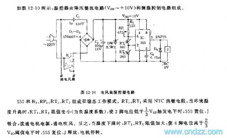
See as Figure 12-10, the temperature controller consists of the step-down rectifier circuit (VDD=+10V) and temperature detection control circuit.
555,R1,RP1,RT1 and RT2 form a dual steady working mode. RT1 and RT2 is made of NTC thermistors, when it gets hotter outside, the resistances of RT1 and RT2 turn lower(the temperature coefficient is negative), which makes the LEV on 2-pin is low than the trigger LEV of 1/3VDD and 555 is offset, J pulls in, the motor power supply is connected. Otherwise, when it's cooler outside, the resistances of RT1 and RT2 are rising,which makes the LEV of 6-pin higher than the threshold value LEV of 2/3VDD, 555 is reset and J is released, so the motor stops.
Reprinted Url Of This Article:
http://www.seekic.com/circuit_diagram/Signal_Processing/The_temperature_controller_circuit_of_555_fans.html
Print this Page | Comments | Reading(3)

Article Categories
power supply circuit
Amplifier Circuit
Basic Circuit
LED and Light Circuit
Sensor Circuit
Signal Processing
Electrical Equipment Circuit
Control Circuit
Remote Control Circuit
A/D-D/A Converter Circuit
Audio Circuit
Measuring and Test Circuit
Communication Circuit
Computer-Related Circuit
555 Circuit
Automotive Circuit
Repairing Circuit
Code: