Signal Processing
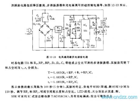
The interval power supply outlet circuit of 555 fans
Published:2011/5/29 7:07:00 Author:Borg | Keyword: power supply outlet | From:SeekIC

The time-based circuit 555, R2,RP1,RP2,D5,D6,C1 and so on consist a multi-resonate oscillator whose duty cycle is adjustable, the shaking period T and duty cycle times t1 and t2 are: T=0.693(R2+RP1+R3+RP2)C1 t1=0.693(R2+RP1)C1 T2=0.693(R3+RP2)C1The longest period of the figured parameter is 300s(5min), and the positive and the negative times (i.e on/off time) of the pulse are 150s,respectively. The period span and duty cycle can be adjusted by RP1 and RP2. The lighting or not of LED means on or off, respectively. SSR is fixed with IC solid relay TAC018(IA), which has advantages of photo-electricity separation and safety.
Reprinted Url Of This Article:
http://www.seekic.com/circuit_diagram/Signal_Processing/The_interval_power_supply_outlet_circuit_of_555_fans.html
Print this Page | Comments | Reading(3)

Article Categories
power supply circuit
Amplifier Circuit
Basic Circuit
LED and Light Circuit
Sensor Circuit
Signal Processing
Electrical Equipment Circuit
Control Circuit
Remote Control Circuit
A/D-D/A Converter Circuit
Audio Circuit
Measuring and Test Circuit
Communication Circuit
Computer-Related Circuit
555 Circuit
Automotive Circuit
Repairing Circuit
Code: