© 2008-2012 SeekIC.com Corp.All Rights Reserved.
Signal Processing
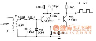
50Hz rectangular wave generator circuit
Published:2011/6/13 6:59:00 Author:Christina | Keyword: 50Hz, rectangular wave, generator | From:SeekIC

The figure shows the Schmidt shaping circuit that changes the sinusoidal voltage into the rectangular wave. The sinusoidal voltage which is reduced by the transformer adds to the base electrode of VT1 directly. In the positive half cycle of the alternating current, the diode VD conducts, the base electrode electric potential of VT1 is positive, so the VT1 cuts off, VT2 conducts. In the negative half cycle of the alternating current, the base electrode electric potential of VT1 is negative, VT1 conducts and the 5OHz rectangular wave is output by the collector electrode of VT2.
Figure The 50Hz rectangular wave generator circuit
Reprinted Url Of This Article:
http://www.seekic.com/circuit_diagram/Signal_Processing/50Hz_rectangular_wave_generator_circuit.html
Print this Page | Comments | Reading(3)

Article Categories
power supply circuit
Amplifier Circuit
Basic Circuit
LED and Light Circuit
Sensor Circuit
Signal Processing
Electrical Equipment Circuit
Control Circuit
Remote Control Circuit
A/D-D/A Converter Circuit
Audio Circuit
Measuring and Test Circuit
Communication Circuit
Computer-Related Circuit
555 Circuit
Automotive Circuit
Repairing Circuit
New published articles
Response in 12 hours

Code: