Signal Processing
The rectangle pulse frequency doubler
Published:2011/6/17 9:01:00 Author:Borg | Keyword: rectangle pulse, frequency doubler | From:SeekIC

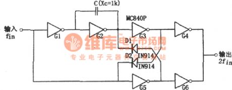
In the figure is the rectangle pulse frequency doubler circuit. This circuit is a digital frequency doubler, which consists of a 6-inverting-phaser MC840P, 2 diodes and a capacitor, and its working frequency is 1Hz~100KHz. The input signal of the circuit is a square wave, and the output is an approximately symmetric rectangle wave. The required capacitive reactance of capacitor C at the frequency is 1kΩ. If the required output is a symmetric square wave, we can connect the capacitor with a resistor in serial or parallel way. The output circuit includes the phase inverters of G3, G4, G5 and G6, and they are coupled by the diodes of D1 and D2.
Reprinted Url Of This Article:
http://www.seekic.com/circuit_diagram/Signal_Processing/The_rectangle_pulse_frequency_doubler.html
Print this Page | Comments | Reading(3)

Article Categories
power supply circuit
Amplifier Circuit
Basic Circuit
LED and Light Circuit
Sensor Circuit
Signal Processing
Electrical Equipment Circuit
Control Circuit
Remote Control Circuit
A/D-D/A Converter Circuit
Audio Circuit
Measuring and Test Circuit
Communication Circuit
Computer-Related Circuit
555 Circuit
Automotive Circuit
Repairing Circuit
Code: