Signal Processing
555 acupuncture point detector circuit
Published:2011/5/23 7:48:00 Author:TaoXi | Keyword: acupuncture point, detector | From:SeekIC

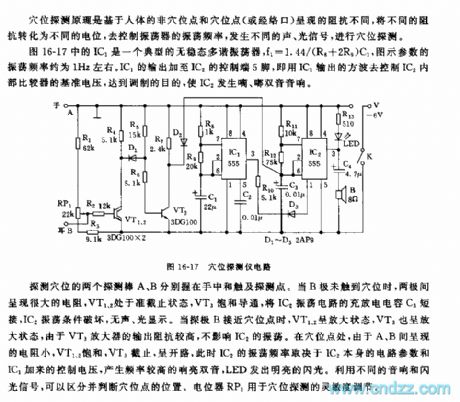
As the figure 16-17 shows, IC1 is a typical astable multivibrator, f1=1.44/(R8+2R9)C1, the parameters' oscillation frequency in the figure is about 1Hz. IC1's output adds to the pin-5of IC2's control port, that uses IC1's output square wave to control IC2 internal comparator's reference voltage, so we achieve the purpose of modulation, IC2 sends out the diplophonia of di du .
At the acupuncture point, the resistance between A and B is small, so VT1 and VT2 is saturated, VT3 cuts off, at this time IC2's oscillation frequency depends on the circuit parameters of IC2 itself and the control voltage of IC1, this circuit produces the higher frequency loud diplophonia, and the LED issues the flashlight.
Reprinted Url Of This Article:
http://www.seekic.com/circuit_diagram/Signal_Processing/555_acupuncture_point_detector_circuit.html
Print this Page | Comments | Reading(3)

Article Categories
power supply circuit
Amplifier Circuit
Basic Circuit
LED and Light Circuit
Sensor Circuit
Signal Processing
Electrical Equipment Circuit
Control Circuit
Remote Control Circuit
A/D-D/A Converter Circuit
Audio Circuit
Measuring and Test Circuit
Communication Circuit
Computer-Related Circuit
555 Circuit
Automotive Circuit
Repairing Circuit
Code: