Signal Processing
Optical Fiber Data Transmission Coupling Circuit
Published:2011/5/17 1:21:00 Author:Sharon | Keyword: Optical Fiber, Data Transmission, Coupling | From:SeekIC

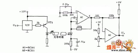
The first step is to transform input analog signal to frequency signal through input voltage frequency converter V/F and then send it to optical fiber by light-emitting diodes. The length of optical fiber or polystyrene rod depends on the separative voltage between digital or analog signals and the photodiode. Photodiode can drive a 100mA output operational amplifier A1, and can further drive cables, relays, or loudspeaker after being amplified byop-amp A2. LEDs can apply MV50 with output amount to 200mA. A1 can apply RC301 operational amplifier, and A2 RC311 can use operational amplifier.
Reprinted Url Of This Article:
http://www.seekic.com/circuit_diagram/Signal_Processing/Optical_Fiber_Data_Transmission_Coupling_Circuit.html
Print this Page | Comments | Reading(3)

Article Categories
power supply circuit
Amplifier Circuit
Basic Circuit
LED and Light Circuit
Sensor Circuit
Signal Processing
Electrical Equipment Circuit
Control Circuit
Remote Control Circuit
A/D-D/A Converter Circuit
Audio Circuit
Measuring and Test Circuit
Communication Circuit
Computer-Related Circuit
555 Circuit
Automotive Circuit
Repairing Circuit
Code: