Signal Processing
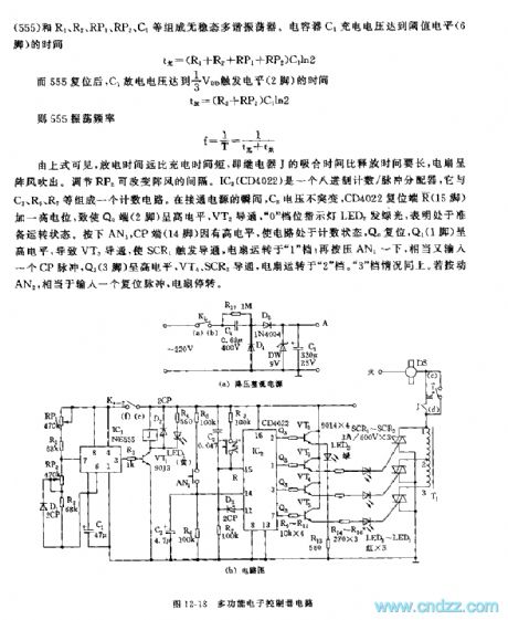
The 555 multi-functional electric control circuit
Published:2011/5/28 21:03:00 Author:Borg | Keyword: multi-functional, electric control | From:SeekIC

See as the above equations, the discharging time is longer that charging time,i.e the pulling time of relay J is longer than its releasing time, the fan generates gusts. And the intervals of the gusts can be changed by adjusting RP2. IC2(CD4022) is a octal counter/pulse distributor, which consists a counting circuit with C2,R5,R7 and so on. At the moment of power-on, the voltage on C2 doesn't mutate, and the reset terminal(R) (15-pin) of CD4022 is imposed with a high LEV, which lead to the high LEV of Q0 terminal(2-pin), and VT2 is conducting and the indicating LED2 of 0 gear glows green beams that means it is ready to run.
Reprinted Url Of This Article:
http://www.seekic.com/circuit_diagram/Signal_Processing/The_555_multi_functional_electric_control_circuit.html
Print this Page | Comments | Reading(3)

Article Categories
power supply circuit
Amplifier Circuit
Basic Circuit
LED and Light Circuit
Sensor Circuit
Signal Processing
Electrical Equipment Circuit
Control Circuit
Remote Control Circuit
A/D-D/A Converter Circuit
Audio Circuit
Measuring and Test Circuit
Communication Circuit
Computer-Related Circuit
555 Circuit
Automotive Circuit
Repairing Circuit
Code: