Signal Processing
555 electronic ballast circuit
Published:2011/5/24 2:52:00 Author:TaoXi | Keyword: electronic, ballast | From:SeekIC

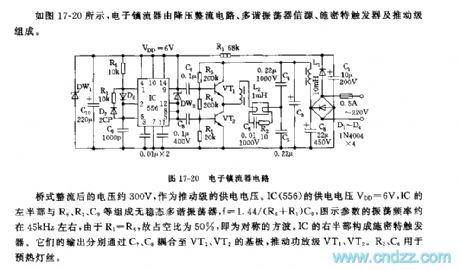
As the figure 17-20 shows, the electronic ballast is composed of the step-down rectifier circuit, the multivibrator source circuit, the Schmitt trigger and the promotion stage.
The bridge rectifying voltage is 300V, and this voltage is used as the promotion stage's power supply voltage. IC(556)'s power supply voltage VDD=6V, the left part of IC and the R6,R1,C9 constitute the astable multivibrator, the oscillation frequency f=1.44/(R6+R1)C9, the parameters of the figure's oscillation frequency is about 45kHz, because R1=R6, so the duty cycle is about 50%, it is the symmetrical square wave. The right part of the IC constitutes the Schmitt trigger.
Reprinted Url Of This Article:
http://www.seekic.com/circuit_diagram/Signal_Processing/555_electronic_ballast_circuit.html
Print this Page | Comments | Reading(3)

Article Categories
power supply circuit
Amplifier Circuit
Basic Circuit
LED and Light Circuit
Sensor Circuit
Signal Processing
Electrical Equipment Circuit
Control Circuit
Remote Control Circuit
A/D-D/A Converter Circuit
Audio Circuit
Measuring and Test Circuit
Communication Circuit
Computer-Related Circuit
555 Circuit
Automotive Circuit
Repairing Circuit
Code: