Signal Processing
555 snore suppressor circuit
Published:2011/5/29 20:41:00 Author:TaoXi | Keyword: 555, snore, suppressor | From:SeekIC

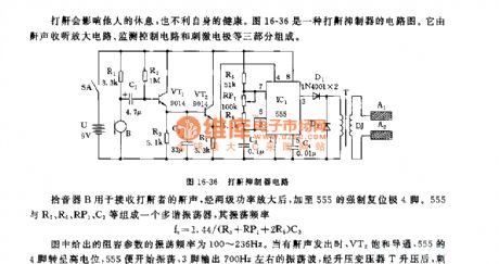
The figure 16-36 shows the snore suppressor circuit, it is composed of the snore receiving circuit, the monitoring control circuit and the stimulating circuit.
The pickup B can be used to receive the snore, the snore is amplified by the two stages power tube, then it adds to the mandatory resetting port pin-4. The multivibrator is composed of the 555 and R5,R6,RP1,C3, the oscillation frequency f=1.44/(R5+RP1+2R6)C3.
The RC parameters' oscillation frequency is 100~236Hz. When there is the snore, VT2 conducts, pin-4 of 555 has the high electric potential, the 555 starts working, pin-3 outputs the 700Hz oscillating wave, and this oscillating wave is boosted by the pressurization transformer T to stimulate both ends of the electrode DJ to produce the 45V electrical pulse.
Reprinted Url Of This Article:
http://www.seekic.com/circuit_diagram/Signal_Processing/555_snore_suppressor_circuit.html
Print this Page | Comments | Reading(3)

Article Categories
power supply circuit
Amplifier Circuit
Basic Circuit
LED and Light Circuit
Sensor Circuit
Signal Processing
Electrical Equipment Circuit
Control Circuit
Remote Control Circuit
A/D-D/A Converter Circuit
Audio Circuit
Measuring and Test Circuit
Communication Circuit
Computer-Related Circuit
555 Circuit
Automotive Circuit
Repairing Circuit
Code: