Signal Processing
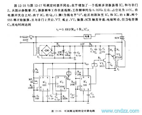
The 555 discontinuous running timer circuit
Published:2011/5/30 3:34:00 Author:Borg | Keyword: discontinuous, timer circuit | From:SeekIC

The the difference between adjustable timers in Figure 12-18 and Figure 12-17 is that the earlier is added with a low-frequency multi-resonate oscillator IC3 and a NAND. Judging from the parameters in the figure, the oscillation frequency of IC3 is very low, which is about 0.05Hz, and its duty cycle is 50%. When the power supply switch is closing, as Q12(1-pin) of IC2 is at a low LEV 0 , and the LEV is added to the 4-pin of IC1 and IC3 by the inverter, then both of the 555 start to oscillate, and the NAND 2 opens, VT1 is blocked, VT2 shakes, SCR is triggered and conducting, the fan runs.
Reprinted Url Of This Article:
http://www.seekic.com/circuit_diagram/Signal_Processing/The_555_discontinuous_running_timer_circuit.html
Print this Page | Comments | Reading(3)

Article Categories
power supply circuit
Amplifier Circuit
Basic Circuit
LED and Light Circuit
Sensor Circuit
Signal Processing
Electrical Equipment Circuit
Control Circuit
Remote Control Circuit
A/D-D/A Converter Circuit
Audio Circuit
Measuring and Test Circuit
Communication Circuit
Computer-Related Circuit
555 Circuit
Automotive Circuit
Repairing Circuit
Code: