Signal Processing
555 simple electrocardiogram validator circuit
Published:2011/5/25 2:18:00 Author:TaoXi | Keyword: 555, simple, electrocardiogram, validator | From:SeekIC

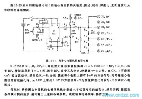
The figure 16-15 shows the validator that can be used to check the sensitivity, the damping, the linearity, the difference distinguishing ratio, the paper passing speed and the guide line connection of the electrocardiogram validator.
The astable multivibrator is composed of the IC(555) ad RP1, R1, RP2, C1, the T=0.693(RP1+RP2+R1)C1. By adjusting RP1, the oscillation period T=0.6 second, and you can change the duty ratio by adjusting RP2, then the pulse width will be 0.2 second. You can get the 4mV square wave signal from CK3. This square wave signal is separated by R4~R7, so each resistance has the square wave signal of 1 mV. You can get out the 1.5V square wave signal from the LED as the difference ratio measurement signal to set the electrocardiogram device.
Reprinted Url Of This Article:
http://www.seekic.com/circuit_diagram/Signal_Processing/555_simple_electrocardiogram_validator_circuit.html
Print this Page | Comments | Reading(3)

Article Categories
power supply circuit
Amplifier Circuit
Basic Circuit
LED and Light Circuit
Sensor Circuit
Signal Processing
Electrical Equipment Circuit
Control Circuit
Remote Control Circuit
A/D-D/A Converter Circuit
Audio Circuit
Measuring and Test Circuit
Communication Circuit
Computer-Related Circuit
555 Circuit
Automotive Circuit
Repairing Circuit
Code: