Signal Processing
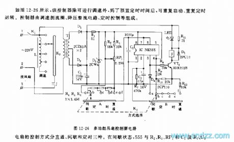
The 555 multi-functional ceiling fan controller circuit
Published:2011/5/28 21:24:00 Author:Borg | Keyword: multi-functional ceiling fan | From:SeekIC

The fan control method is classified into three ways that are direct, interval and timing. In the interval state, 555,R2,R3,RP1,C2,R7,C3 and so on consists a non-steady multi-resonate oscillator, before the charging voltage reaches the trigger LEV(2/3VDD), the 3-pin of 555 is in a high LEV, VT1 is conducting, the relay J pulls in, the fan gets power and starts to run, the running time is determined by R2,R3,RP1 and C2, in the figure, the corresponding time to the parameters is around 25~60s. The interval time means the period after 555 is reset, and C2 discharges(with the help of R7) to the the trigger LEV of 2-pin(1/3VDD), the time span corresponding to the parameter in the figure is about 20s.
Reprinted Url Of This Article:
http://www.seekic.com/circuit_diagram/Signal_Processing/The_555_multi_functional_ceiling_fan_controller_circuit.html
Print this Page | Comments | Reading(3)

Article Categories
power supply circuit
Amplifier Circuit
Basic Circuit
LED and Light Circuit
Sensor Circuit
Signal Processing
Electrical Equipment Circuit
Control Circuit
Remote Control Circuit
A/D-D/A Converter Circuit
Audio Circuit
Measuring and Test Circuit
Communication Circuit
Computer-Related Circuit
555 Circuit
Automotive Circuit
Repairing Circuit
Code: