
Circuit Diagram
Index 628
REMOTE_FINE_TUNING
Published:2009/7/14 4:36:00 Author:May

Addition of voltage-variable capacitance diode to crystal feedback path provides capacitance range of 50 to 12 pF with tuning voltage range of 0-30 V. Diode supplements 2-60 pF trimmer capacitor that adjusts oscillator frequency with respect to control-voltage input. Inverting input of A1 connects to reference voltage VBB, which is available on pin of MC10116 and is center volt-age of output signal swing of amplifier. A2 is connected as Schmitt trigger to give high-speed rise and fall times. Frequency deviation on either side of center is function of crystal frequency and ranges from±50 to±300 PPM for crystals between 1 and 20 MHz.-B. Blood, Fine-Tune This Oscillator with Voltage, EDN Magazine, Aug. 5, 1978, p 74. (View)
View full Circuit Diagram | Comments | Reading(875)
l_MA_CONSTANT_CURRENT_SCR_SOURCE
Published:2009/7/14 4:35:00 Author:May

Use of high-breakdown-voltage 2N1599 scr gives 0.25% regulation at 1 ma for input volt-ages of 10 to 400V. Output current can be adjusted up to 10%. Differential amplifier Q1-Q2 compares sampled output current with voltage across reference zener.-R. H. Crawford, 400-Volt SCR Constant-Current Source, EEE, 12:3, p74. (View)
View full Circuit Diagram | Comments | Reading(974)
PC_TEMPERATURE_INTERFACE
Published:2009/7/14 4:35:00 Author:May


This simple temperature interface covers a range of 0 to 51°C. Dual balanced 12-V supplies were used to power the prototype, but dual 5-V supplies should just about suffice. IC1 is the temperature sensor. Over this range of temperatures, the LM35CZ should work well. The output from IC1 feeds into a noninverting-mode amplifier based on IC2. The closed-loop voltage gain of the amplifier is set by resistors R1 and R2 and preset VR1. The latter is adjusted to give a voltage gain of 5. VR1 is given the correct setting by first subjecting the sensor to a temperature, which is equal to about 50 or 100 percent of the full-scale value (i.e., about 20 to 51°C.). In most cases, the room temperature will be about 20 to 25°C, which will suffice. An accurate thermometer is used to measure the room temperature, and then VR1 is adjusted for the appropriate reading.
The following GW Basic or Q BASIC program reads the temperature sensor and prints the temperature on the screen: (View)
View full Circuit Diagram | Comments | Reading(1662)
DECOUPLING_FOR_PULSE_DELAY
Published:2009/7/15 3:39:00 Author:Jessie

Coupling circuit ahead of input-inverting digital pulse delay prevents C1 from loading driving collector and decreases noise sensitivity.-R. A.Karlin, One-Transistor Multi Delays Digital Pulses, Electronics, 38:17, p 85-86. (View)
View full Circuit Diagram | Comments | Reading(579)
INTEGRATOR_OF_SOLID_STATE_PHANTASTRON
Published:2009/7/15 3:38:00 Author:Jessie

Q2 and Q3 provide open-loop gain, while R4 and C1 are feedback elements.-S. R. Parris and D. A Staar, Highly Accurate Phantastron Delay Circuit, Electronics, 33:43, p 72-74. (View)
View full Circuit Diagram | Comments | Reading(579)
ABSOLUTE_VALUES_1
Published:2009/7/15 3:38:00 Author:Jessie

Opamps A1 and A2 act with PNP transistors Q4 and Q5 to form operational rectifier having current-mode output. Current-to-voltage converter A3 uses R2 asscale factor. Input voltage range is determined by common-mode range of opamp and breakdown ratings of components. Circuit shown handles ±10 V signal.-S, Smith, Full-Wave Rectifier Needs Only Two Precision Resistors, EDN Magazine, Jan. 5, 1975, p 56. (View)
View full Circuit Diagram | Comments | Reading(819)
THYRATRON_AFC_FOR_AIRBORNE_RADAR
Published:2009/7/15 3:38:00 Author:Jessie

Uses Weiss discriminator, which for large bandwidths is easier to adjust than Foster-Seeley, and requires no special i-f transformer. Employs two thyratrons to generate required control voltage for repeller of klystron. -NBS, Handbook Preferred Circuits Navy Aeronautical Electronic Equipment, Vol. I, Electron Tube Circuits,1963, p N 13-4. (View)
View full Circuit Diagram | Comments | Reading(1066)
TONE_BURST_GENERATOR
Published:2009/7/15 3:37:00 Author:Jessie

One section of 556 dual timer is connected as mono MVBR and other section as oscillator. Pulse established by mono turns on oscillator, allowing generation of AF tone burst.- Signetics Analog Data Manual, Signetics, Sunnyvale, CA, 1977, p 723-724. (View)
View full Circuit Diagram | Comments | Reading(2896)
FOUR_QUADRANT_SIGNAL_MULTIPLIER
Published:2009/7/15 3:36:00 Author:Jessie

Highspeed magnetic-amplifier square-law circuits with silicon diodes and resistors replace slow-response thermal converters in. four-quadrant analog multiplying device. Polarity-reversible signal currents I1 and I2 cre multiplied with two square-law and two push-pull magnetic amplifier circuits. Reversible-polarity output drives ink oscillograph. -W. A. Geyger, Multiplying Circuit Uses Magnetic Amplifiers, Electronics, 32:2, p 58-59. (View)
View full Circuit Diagram | Comments | Reading(1848)
COLLECTOR_VOLTAGE_CONTROL_AFC_OSCILLATOR
Published:2009/7/15 3:36:00 Author:Jessie

Afc input signal acts through series resistor to vary collector voltage of 40.Mc oscillator. Sensitivity is 2.5 Mc per V. Bias network adjustment is critical.-T. P. Prouty, Using Varactors to Extend Frequency-Control Range, Electronics, 36:45, p 48-49. (View)
View full Circuit Diagram | Comments | Reading(638)
SUBAUDIO_T0_20_MHz
Published:2009/7/15 3:36:00 Author:Jessie

Square-wave signal source covers wide frequency range in fully tunable decade steps, as TTL signal source for experimentation with counters, microprocessors, and other logic circuits. Uses tunable 2N2222 transistor oscillator operating at 10-20 MHz, with switchable decade dividers for range selection and switchable binary dividers for band selection. Article covers construction and calibration,-A. G. Evans, Digital Signal Source, 73 Magazine, Dec. 1977, p 150-151.
(View)
View full Circuit Diagram | Comments | Reading(1039)
VARACTOR_CONTROLLED_40_MC_OSCILLATOR_
Published:2009/7/15 3:35:00 Author:Jessie

Oscillator transistor also acts as a d-c amplifier between afc input and varactor diode to give electronic tuning over range of 11 Mc with sensitivity of 5.8 Mc per v.-T. P. Prouty, Using Varactors to Extend Frequency-Control Range, Electronics, 36:45, p 48-49. (View)
View full Circuit Diagram | Comments | Reading(678)
CHROMA_PROCESSOR
Published:2009/7/15 3:04:00 Author:Jessie
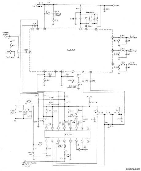
Combination of RCA CA3121E chroma amplifier/demodulator and CA3070 chroma signal processor provides automatic chroma control and color killer sensing along with other functions required for high-level B - Y, R - Y, and G - Y color difference signals having low impedances for driving highlevel R, G, and B output amplifiers.- Linear Integrated Circuits and MOS/FET's, RCA Solid State Division, Somerville, NJ, 1977, p 359-360. (View)
View full Circuit Diagram | Comments | Reading(888)
BALANCED_PARAMETRIC_DOUBLER
Published:2009/7/15 3:04:00 Author:Jessie
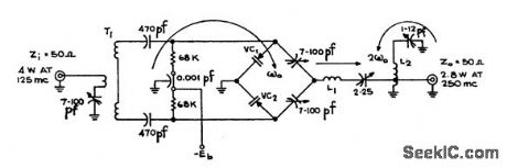


Handles twice the power of single-ended circuit using same varactor diode, while doubling 125-Mc input. Varactors VC are PSI type PC116.Efficiency is 70%. Transformer winding data is given in article.-R. D. Gromer, VHF Balanced Parametric Doubler, EEE, 11:8, p 30-31. (View)
View full Circuit Diagram | Comments | Reading(623)
A_C_OPERATED_TIME_DELAY
Published:2009/7/15 3:03:00 Author:Jessie

Switch is normally closed, charging C and blocking scs.Delay is initiated by opening switch. After delay interval, determined by R, Q, and potenliometer, silicon controlled switch conducts on altenate half-cycles. Transistor Manual, Seventh Edition, General Electric Co., 1964, p 435. (View)
View full Circuit Diagram | Comments | Reading(649)
VHF_VARACTOR_QUADRUPLER
Published:2009/7/15 3:03:00 Author:Jessie

Supplies 160 Mc at up to 0.5 w. Output impedance is 50 ohms.-R. C. Wonson, Designing VHF Valactor Multipliers, FEE, 11;12, p 48-52. (View)
View full Circuit Diagram | Comments | Reading(584)
CURRENT_AMPLITUDE_DETECTOR
Published:2009/7/14 4:32:00 Author:May

Used to indicate when pulsed drive currents for memory array exceed tolerance limits. Can detect current pulse deviation of 10 ma from 1.2-amp current Amplitude Detector, EEE.12:11,p68-70 . (View)
View full Circuit Diagram | Comments | Reading(889)
A_F_DOUBLER
Published:2009/7/15 3:03:00 Author:Jessie
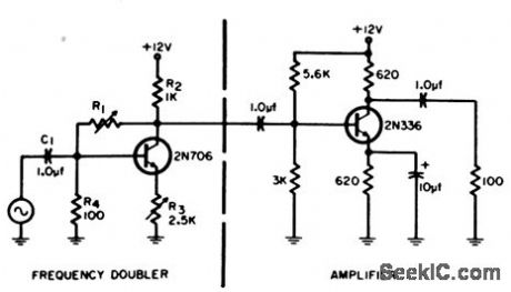
Frequency of sinusoidal signal is doubled with only one transistor, one coupling capacitor, and four resistors, by utilizing nonlinear characteristic of transistor for half-wave rectification. Purity of output waveform is adjusted with feedback control R1.-R. J. Miller, Jr., Audio Frequency Doubling Without Bulky filters, EEE, 12:12, p 57. (View)
View full Circuit Diagram | Comments | Reading(723)
THREE_PHASE_PULSE_GENERATOR
Published:2009/7/15 3:03:00 Author:Jessie

Requires only CMOS 4-bit shift register and two CMOS inverters. Register is connected to operate as divide-by-6 Johnson counter giving glitch-free outputs. Circuit is driven by square-wave clock signal having frequency 6 times that of desired output frequency.-C. Rutschow, Simple CMOS Circuit Generates 3-Phase Signals, EDN Magazine, June 20, 1976, p 128. (View)
View full Circuit Diagram | Comments | Reading(3024)
50_MC_TO_100_MC_VARACTOR_DOUBLER
Published:2009/7/15 3:02:00 Author:Jessie
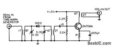
Used to extend usefulness of conventional time marker generator.-R. M. Zilberstein, Frequency Doublet and Amplifier, EEE, 12:12, p 57. (View)
View full Circuit Diagram | Comments | Reading(684)
| Pages:628/2234 At 20621622623624625626627628629630631632633634635636637638639640Under 20 |
Circuit Categories
power supply circuit
Amplifier Circuit
Basic Circuit
LED and Light Circuit
Sensor Circuit
Signal Processing
Electrical Equipment Circuit
Control Circuit
Remote Control Circuit
A/D-D/A Converter Circuit
Audio Circuit
Measuring and Test Circuit
Communication Circuit
Computer-Related Circuit
555 Circuit
Automotive Circuit
Repairing Circuit