
Circuit Diagram
Index 631
MICROWAVE_KLYSTRON_AFC
Published:2009/7/15 3:32:00 Author:Jessie

Uses signal from discriminator of 6,000-Mc microwave receiver to stabilize frequency of local-oscil-lator klystron. Balanced silicon-diode input chopper lattice is excited at 3.5 kc, but only error signal from discriminator will unbalance network and pass 3.5 kc on to error amplifier.-M. C. Harp, Nonvacuum Devices Control Klystrons, Electronics, 32;7, p 68-70. (View)
View full Circuit Diagram | Comments | Reading(1526)
OPAMP_ELECTROMETER
Published:2009/7/15 3:32:00 Author:Jessie

Use of FET input keeps input bias current down to 20 femtoamperes, with common-mode input resistance of 1015 ohms. Uses Analog Devices AD 832 dual JFET Q1-Q2 in source-follower connection, with low-cost general-purpose AD 3958 dual FET generating operating current and providing bootstrapping for Q1-Q2. Article covers guarding techniques used to minimize leakage currents.-J. Dostal, Electrometer Boasts Low Bias Current, EDN Magazine, Jan. 20, 1977, p 90 and 92. (View)
View full Circuit Diagram | Comments | Reading(3057)
400_cps_INVERTER_POWER_AMPLIFIER
Published:2009/7/15 3:32:00 Author:Jessie

Has low internal impedance and low distortion, to Provide good output voltage regulation for d-c to 400-cps a-c inverter. Uses com pounded common-collector output stage. Delivers 55 w at 400-cps with only 2.4% total harmonic distortion.. -R. Wileman, Linear Circuits Regulate Solid-state Invertel, Electronics,33:16,p6l-63. (View)
View full Circuit Diagram | Comments | Reading(1096)
TEMPERATURE_TO_FREQUENCY_CONVERTER_CIRCUIT
Published:2009/7/14 4:23:00 Author:May

IC1 produces the Fahrenheit-dependent voltage at its output. This is fed into the LM331 VFC through precision resistor R1. Inside IC2 are a switched current source, an input comparator, and a one-shot timer. The input comparator is designed to produce a trigger pulse if the voltage at pin 7 is greater than the voltage at pin 6. It does this by comparing the two voltages, one of which is generated internally by the switched current source, and the other of which is obviously the input. The switched current source charges capacitor C3. When the comparator trips and produces its trigger pulse, it activates the monostable multivibrator, which outputs a positive pulse that turns on the out-put transistor. The monostable multivibrator turns on the switched current source for a period of 1.1 times RC, where RC is the combination of resistor R5 and capacitor C4. C1 charges up to a point where it exceeds the input voltage, and the comparator resets itself; thus the frequency output transistor Q1 will be turned off. Resistor R2 discharges C3 in a time interval that depends on the values of both components. Then, the input comparator and monostable multivibrator are reset, and an-other cycle will be implemented as long as there is sufficient input voltage. Finally, resistors R4 and VR1 set the amount of current the constant-current source is able to inject into C3. Thus, VR1 can set the response span of the IC by adjusting it. 103, two gates of a hex Schmitt trigger, are used to buffer IC2's output to light an LED and to make available a digital signal, Remember two things about IC3: Its logic 1 output will be a full9V, not the TTL level of 5 V, and all unused inputs must be tied to ground to prevent self-oscillation at RF frequencies and consequent malfunction of the circuit. (View)
View full Circuit Diagram | Comments | Reading(1340)
FAST_SETTLING_COAX_DRIVER
Published:2009/7/14 4:22:00 Author:May

Suitable for use as radar pulse driver, video sync driver, or pulse-amplitude-modulation line driver. Uses Harris HA-2530/2535 wideband amplifier having high slew rate. Usable bandwidth is about 100 kHz when connected for noninverting operation as shown. Driver output is 60 mA into 60-ohm load. 5% settling time is 60 ns.- Linear & Data Acquisition Products, Harris Semiconductor, Melbourne, FL, Vol. 1, 1977, p 7-54 (Application Note 516). (View)
View full Circuit Diagram | Comments | Reading(958)
LOW_COST_STROBE
Published:2009/7/14 4:22:00 Author:May

Addition of silicon controlled rectifier in triggering circuit of $20 automobile engine-timing strobe gives low-cost general-purpose stroboscope. Modification is completed by wrapping ten turns of No. 18 bare copper wire around flashtube and connecting one end to photoflash transformer T1, with other end unconnected. Can be triggered by 10-microsec 3.v pulse at 5 ma, up to 25 times per second. Flash duration is 100 microsec .-A. C. Eberle , low-Cost Strobe Built with SCR in Trigger, Electronics, 39:14, p 80-81. (View)
View full Circuit Diagram | Comments | Reading(1578)
MISSING_PULSE_DETECTOR
Published:2009/7/15 3:32:00 Author:Jessie

Timing cycle of 555 timer is continuously reset by input pulse train. Change in input frequency or missing pulse allows completion of timing cycle, producing change in output level. Component values should be chosen so time delay is slightly longer than normal time between pulses.- Signetics Analog Data Manual, Signetics, Sunnyvale, GA, 1977, p 723. (View)
View full Circuit Diagram | Comments | Reading(4086)
ADJUSTABLE_STROBE
Published:2009/7/14 4:21:00 Author:May

Provides time-motion data not possible with ordinary strobe. Used in studying motions where velocity varies during cycle, as in sewing machines, switches, relays, motors, and vibrating parts. Viewer can change motion point being studied by turning switch that gives choke of l00 different viewing positions.-J. H. Blakeslee, Strobe Techniques Analyze Complex Mechanical Motion, Electronics, 32:23, p 62-64. (View)
View full Circuit Diagram | Comments | Reading(690)
TRIGGERED_BLOCKING_OSCILATOR
Published:2009/7/14 4:20:00 Author:May

Gives pair of output pulses, with opposite polarity, for controlling timing and spacing of flashes.-P. Scott, Microflash and Pulse Stimulator Tests Human Optical Response, Electronics, 34:27, p 48-51. (View)
View full Circuit Diagram | Comments | Reading(715)
_12_V_AT_300_mA_FROM__48_V
Published:2009/7/14 4:20:00 Author:May

Uses Fairchild μA78S40 switching regulator having variety of internal functions that can provide differing voltage step-up, step-down, and inverter modes by appropriately connecting external components. Efficiency is 86%, and output ripple is 300 mV. Extra opamp on chip is used to derive required reference voltage of -2.6 V from internal :.3-V reference.-R. J. Apfel and D. B. Jones, Universal Switching Regulator Diversifies Power Subsystem Applications, Computer Design, March 1978, p 103-112. (View)
View full Circuit Diagram | Comments | Reading(471)
BANDPASS_ORIGINATE_FILTER
Published:2009/7/14 4:19:00 Author:May

Provides gain of over 15 dB between 1975 and 2275 Hz, to accept 2025-2225 Hz, signals of low-speed modem system using Motorola MC6860 IC,-J. M. DeLaune, “Low-Speed Modem System Design Using the MC6860,”Motorola, Phoenix, AZ、1975, AN-747, p13 (View)
View full Circuit Diagram | Comments | Reading(694)
STROBE_OSCILLAIOR_TRIGGER
Published:2009/7/14 4:19:00 Author:May

Oscillator produces square pulses having short rise time, over total frequency range of 200 to 1. Osdllator may also be sychronized to power line. Schmitt trigger provides additional means of getting output pulse to drive Eccles-Jordan trigger that provides alternate pulses for two shored-cycle strobe lamps.-L. H. Barrett, New Circuit Improves Stroboscope Versatility, Electronics, 32:32, p 116-118. (View)
View full Circuit Diagram | Comments | Reading(603)
7_DIGIT_BINARY_COUNTER
Published:2009/7/14 4:19:00 Author:May

Stores pulses re calved from oscillator gate. 128th pulse resets counter to zero. Complete binary counter consists of seven cascaded bistable multivibrators, transformer-triggered.-W. W. Grannemann et al, Pulse-Height-to-Digital Signal Converter, Electronics, 33:2, p 58-60. (View)
View full Circuit Diagram | Comments | Reading(1042)
DIGITALLY_CONTROLLED_VARIABLE_LOW_PASS
Published:2009/7/14 4:18:00 Author:May

DG201 CMOS analog switch with TTL control permits setting of break frequency at 1, 10, 100, or 1000 Hz. Voltage gain below break frequency, determined by ratio of R3 to R1, is 100 (40 dB). Highest break frequency (1000 Hz) is obtained when C4 is switched in.- Analog Switches and Their Applications, Siliconix, Santa Clara, CA, 1976, p 7-66-7-67. (View)
View full Circuit Diagram | Comments | Reading(745)
ROTATING_BEACON
Published:2009/7/14 4:18:00 Author:May

Four lamps flash one at a time, beginning with lamp 1, when power is applied, to simulate rotating light for emergency vehicles. R1 controls speed.-D. V. Jones, Quick-On-The-Trigger Design, Electronics, 38:12, p 105-110. (View)
View full Circuit Diagram | Comments | Reading(1318)
TEMPERATURE_ADAPTER_FOR_DVM
Published:2009/7/14 4:18:00 Author:May

A schematic for the temperature adapter is shown. The circuit outputs 0.01 V/°F. To determine temperature, you ignore the decimal point in the display, and the temperature readout is to the tenth of a degree. For example, if the temperature in a room is 75.5°, your DMM would read +0.755 V. The voltage input for op amp IC1 is obtained from a transistor Q1 used as a diode in this application. The linear voltage drop is measured and used to indicate temperature. The low-power regulator LM78L05 (IC2) provides a fixed 5-V source for the circuit. The voltage drop across Q1 is detected and amplified by IC1, an LM1458 op amp. The output of IC1 is then fed to the input terminals of a DMM. Put the positive lead of a voltmeter on pin 7 of IC1, and the negative lead on ground. Adjust R2 for a reading of 2.5 to 3 V. Connect the output of the adapter circuit to a voltmeter set to the 2-V dc scale. Adjust R8 so that the multimeter reads the same as a stabilized thermometer in the same vicinity as the temperature probe (ignore the decimal point). (View)
View full Circuit Diagram | Comments | Reading(1184)
NIXIE_TUBE_RING_COUNTER
Published:2009/7/14 4:18:00 Author:May

Uses silicon controlled switches.- Transistor Manual, General Electric Co. 1964, p430. (View)
View full Circuit Diagram | Comments | Reading(882)
HIGH_VOLTAGE_NEGATIVE_SWITCHING
Published:2009/7/14 4:18:00 Author:May

Uses zener to reduce supply voltage to acceptable level for LM304 IC regulator,Base drive and voltage isolation are provided by Q2, R10, and R11 for PIC636 hybrid power switch Circuit operates in fixed OFF-time mode, -L. Dixon and R. Patel, Designers' Guide to:Switching Regulators, EDN Magazine. Oct. 20, 1974, p 53-59. (View)
View full Circuit Diagram | Comments | Reading(661)
ANSWER_MODEM
Published:2009/7/14 4:17:00 Author:May

Transmits on upper channel (mark 2225 Hz and space 2025 Hz) and receives on lower channel (mark 1270 Hz and space 1070 Hz). Buffer and duplexer provide modem interface to transmission network. Bandpass filter allows only desired receive signals to be seen by limiter and demodulator. Motorola MC6860 modem IC contains modulator, demodulator, and supervisory control functions. -G. Nash, Low-Speed Modem Fundamentals, Motorola, Phoenix, M, 1974, AN-731, p6. (View)
View full Circuit Diagram | Comments | Reading(742)
HIGH_VOLTAGE_FLASH_PULSER
Published:2009/7/14 4:17:00 Author:May
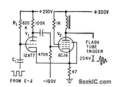
Two identical pulse generators are used to fire two flash tubes alternately lm high-speed strobe. One unit is coupled to each plate of an Eccles-Jordan trigger, to produce required alternating trigger sequence.-L. H. Barrett, New Circuit Improves Stroboscope Versatility, Electronics, 32:32, p 116-118. (View)
View full Circuit Diagram | Comments | Reading(740)
| Pages:631/2234 At 20621622623624625626627628629630631632633634635636637638639640Under 20 |
Circuit Categories
power supply circuit
Amplifier Circuit
Basic Circuit
LED and Light Circuit
Sensor Circuit
Signal Processing
Electrical Equipment Circuit
Control Circuit
Remote Control Circuit
A/D-D/A Converter Circuit
Audio Circuit
Measuring and Test Circuit
Communication Circuit
Computer-Related Circuit
555 Circuit
Automotive Circuit
Repairing Circuit