
Circuit Diagram
Index 636
TRIODE_MAGNETOSTRICTION_BANDPASS_FIL_TER
Published:2009/7/14 4:02:00 Author:May

Practical range is from 45 to 300 kc. When filler is used with triode, it serves as stable fixed-frequency oscillator in telemetry command receiver.-E. J. Neville, Jr., Designing Magnetostriction Filters, Electronics, 33:51, p 88-89. (View)
View full Circuit Diagram | Comments | Reading(842)
325_KC_BRIDGED_T_FILTER
Published:2009/7/14 4:02:00 Author:May

Used in magnetometer having large amounts of odd harmonics and only feeble second harmonk at secondary of sensing probe. Permits ampli-flying only second harmonic, without excessive phase shift.-F. Voelker, Magnetometer Makes Continuous Measurements, Electronics, 31:11, p 152-154. (View)
View full Circuit Diagram | Comments | Reading(668)
2_30_MHz_SSB_DRIVER
Published:2009/7/14 4:02:00 Author:May
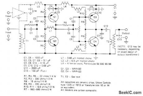
Two-stage complementary-symmetry amplifier combines single-ended impedance matching with high-gain push-pull design to provide up to 25 W PEP for driver applications. Provides good harmonic rejection and low intermodulation distortion. Supply voltage range is 22-30 V. Low-impedance windings of T1 and T2 use 1 turn of copper braid, with 2 turns No. 22 for primary of T1 and 4 turns No. 22 for secondary of T2.-H. Granberg, A Complementary Symmetry Amplifier for 2-30 MHz SSB Driver Applications, Motorola, Phoenix, AZ, 1975, EB-32. (View)
View full Circuit Diagram | Comments | Reading(863)
CONSTANT-CURRENT_LED
Published:2009/7/14 4:01:00 Author:May

National NSL4944 LED having built-in current control features can be used in simple circuit shown to provide current limiting and short-circuit protection for 15-V supply Even、With output shorted, LED draws only a little more than rated current.- Linear Applications、vol. 2, National Semiconductor, Santa Clara, CA, 1976, AN-153,p3 (View)
View full Circuit Diagram | Comments | Reading(1085)
LOW_PASS_SUBAUDIO_FILTER
Published:2009/7/14 4:01:00 Author:May

Gives flat frequency response from d-c to 1-cps cutoff, attenuation slope of 15 db per octave, near zero insertion loss, and good temperature stability.-R. C. Onstad, Low-Pass Filter for Subaudio Frequencies, Electronics, 33:3, p 88-90. (View)
View full Circuit Diagram | Comments | Reading(771)
BIAS_SWITCH
Published:2009/7/14 4:01:00 Author:May

Automatic electronic bias switching improves efficiency of negatively biased linear class B RF power amplifier such as Heath SB-200 because no power is dissipated under no-signal conditions. Transistors are chosen to withstand maximum negative voltages switched, about -150 VDC. Capacitor across collector-base junction of Q1 can be adjusted to reduce turn-on time of switch. With no RE drive from transmitter, amplifier is biased to cutoff and plate current is zero. Switch will operate at RF threshold of about 2 V and apply class B bias voltage to amplifier. As RF drive is increased, plate current increases. With transmitter in SSB mode, plate current is zero with no speech. For speech, plate current increases with RF driving voltage.-F. E. Hinkle, Electronic Bias Switch for Negatively Biased Amplifiers, Ham Radio, Nov, 1976, p 27-29. (View)
View full Circuit Diagram | Comments | Reading(1688)
ZOBEL_LOW_PASS_FILTER
Published:2009/7/14 4:01:00 Author:May

Amide gives design procedure using Caver parameters. Both examples give 40 db attenuation at 5,000 cps when inserted between 600-ohm source and load resistances.-K. Lichtenfeld, Method for Simplifying Filter Design, Electronics, 33:21, p 96-99. (View)
View full Circuit Diagram | Comments | Reading(927)
BALANCED_FET_DC_VOLTMETER
Published:2009/7/15 4:38:00 Author:Jessie

Factory-matched FETs are connected in resistance bridge that is balanced by 814 to make meter read zero for 0-V input voltage. Voltage divider provides eight ranges, using 1% resistors for accuracy. Some must be made up by using two or more resistors in series. Balanced circuit has very low temperature drift, reducing number of times rebalancing is needed.-R. P. Turner, FET Circuits, Howard VV. Sams, Indianapolis, IN, 1977, 2nd Ed., p 119-122. (View)
View full Circuit Diagram | Comments | Reading(1877)
0_TO__63_V_AT_1_A
Published:2009/7/14 4:00:00 Author:May
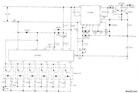
High-voltage digitally controlled power supply uses Motorola MC1406L 6-bit DAC and MC1466L floating voltage regulator to deliver up to 1 A of load current over output voltage that can be incremented in 63 steps of 1 V each, Digital word that controls voltage is coupled into DAC with 4N28 optoisolators. Current-amplifier output stage using Darlington connection of transistors is designed to operate from +70 V supply. -D. Aidridge and N. Wellenstein, Designing Digitally-Controlled Power Supplies, Motorola, Phoenix, AZ, 1975, AN-703, p 6. (View)
View full Circuit Diagram | Comments | Reading(1906)
PARALLEL_T_FILTER_WITH_FEEDBACK
Published:2009/7/14 4:00:00 Author:May

Single-transistor feedback circuit Q2 reduces high attenuation in passband that severely limits conventional 60-cps T-notch filter, Filter response is down 1 db at 62 cps. Can be used in reproducing stereo tape, where it will salvage signals normally buried far below noise level of original tape recording. -J. Strattan , Feedback Improves Filter, Electronics, 39:18, p 99. (View)
View full Circuit Diagram | Comments | Reading(1392)
DIFFERENTIAL_LINE_RECEIVER
Published:2009/7/15 4:36:00 Author:Jessie

Responds to balanced-input drive signals fed to both comparator inputs of 322. Output is undisturbed even with up to 1 V of common-mode noise on input lines. TTL-compatible output is in phase with positive input. Overall delay is about 1 μs.-W. G. Jung, IC Timer Cookbook, Howard W. Sams, Indianapolis, IN, 1977, p 153-155. (View)
View full Circuit Diagram | Comments | Reading(1030)
3_A_LIMITER
Published:2009/7/14 3:59:00 Author:May

Simple current limiter protects itself from over dissipation during shorted output, while handling capacitor or cold-filament loads that momentarily act like shorts. R3 is adjusted so starting current is high enough to begin heating cold filament. As filament voltage increases to about 100 mV, Q4 and Q3 turn off, allowing load current to rise to 3-A limiting value.- L. G. Wright, Short-Protected Current Limiter Ignores Inrush Currents, EEE Magazine, Sept, 1970, p 89-90. (View)
View full Circuit Diagram | Comments | Reading(829)
PULSE_AMPLITUDE_MODULATOR
Published:2009/7/15 4:36:00 Author:Jessie

Used in multiplier that acts with one of operational amplifiers of analog computer. Double-triode V1 here provides pulse-amplitude modulation, for use with separate pulse-width modulator to form desired product of two input variables.-A. J. Ferraro, Multiplier for Analog Computers, Electronics, 33:45, p 73-74. (View)
View full Circuit Diagram | Comments | Reading(1922)
ZOBEL_BAND_ELIMINATION_FILTER
Published:2009/7/14 3:59:00 Author:May

Both examples give at least 40 db attenuation between 8,410 cps and 11,150 cps, for 600-ohm source and load resistances.-K.Lichtenfeld, Method for Simplifying Filter Design, Electronics, 33:21, p 96-99. (View)
View full Circuit Diagram | Comments | Reading(717)
PROBABILITY_MULTIPLIER
Published:2009/7/15 4:34:00 Author:Jessie

Based on converting two analog factors to duty cycles of pulse trains of uncorrelated repetition rate. Pulse-train control of and gate is such that there is no output unless both trains are simultaneously positive, and then average value of gate output is proportional to product. -T. R. Hoffman, Analog Multiplication Using Time as One Variable, Electronics, 33:33, p 136-138. (View)
View full Circuit Diagram | Comments | Reading(779)
ADJUSTABLE_400_CPS_TUNING_FORK_FILTER
Published:2009/7/14 3:59:00 Author:May

Tuning-fork frequency is adjusted by varying current in extra magnet coils facing ends of tines. Current change of 1 ma in frequency-adjust coils gives frequency change of 50 parts per million. Input and output cathode followers isolate filter from rest of circuit. Drive and pickup amplifiers cancel fork insertion loss.-J. J. O'Connor, Tuning-Fork Audio Filter Tunes Electrically, Electronics, 33:49. (View)
View full Circuit Diagram | Comments | Reading(738)
SINGLE_SUPPLY_HIGH_PRECISION_PLL
Published:2009/7/15 4:34:00 Author:Jessie
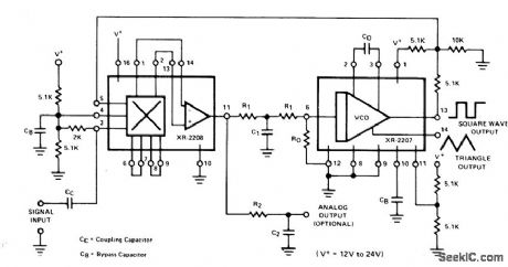
Combination of Exar XR-2207 VCO and XR-2208 operational multiplier is connected for operation from single 12-24 V supply for data communication and signal conditioning applications. Operating frequency range is 0.01 Hz to 100 kHz. Timing resistor R0 should be in range of 5K to 100K, and R1 should be greater than R0 For 10-kHz center frequency, C0 can be 0.01 μF and R0 can be 10K. R1 and C1 which determine tracking range and low-pass filter characteristics, are 45κ and 0.032 μF.- Phase-Locked Loop Data Book, Exar Integrated Systems, sunnyvale, CA, 1978, p62-64 (View)
View full Circuit Diagram | Comments | Reading(1293)
TEMPERATURE_CONTROLLED_FAN
Published:2009/7/14 3:58:00 Author:May

The circuit described here needs only three ICs to smoothly increase fan speed as temperature rises above an easily set trip point. Low-dropout voltage regulator ICl provides power to the fan and to temperature sensor IC2. IC2 drives the middle of the resistor divider across voltage reference IC3.Because the LM45's output stage can only source current, its output voltage will remain at about 610 mV until IC2's temperature rises above 61°C, IC2 will drive the 500-0 Thevenin resistance of the divider, which will cause IC2's supply current to increase rapidly with rising temperature. As the temperature rises above the point where IC2's output voltage exceeds the Thevenin voltage set by R4 and R5, IC2's supply current increases. IC2's supply current flows through Rl and directly affects the regulator's output voltage. If the temperature rises 20°C above the nominal61°C threshold, the regulator's output voltage will rise to 12 V and the fan will operate at full speed. (View)
View full Circuit Diagram | Comments | Reading(178)
HALL_MULTIPLIER_PLATE_DRIVE
Published:2009/7/15 4:33:00 Author:Jessie

Currenl remains in phase with signal from 0 cps to over 20 kc. Distortion is less than 1% over entire range.-R. A. Greiner, Feedbock Amplification Improves Hall-Effect Multipliers, Electronics, 34:34, p 52-55. (View)
View full Circuit Diagram | Comments | Reading(734)
CRYSIAL_RADIOTELEGRAPH_I_F_FILTER
Published:2009/7/14 3:58:00 Author:May

Voltage-controlled varactor diode D1 permits remote location of potentiometer used for phasing adjustment. Circuit can be used for any i-f value from 100 kc to 1.6 Mc by selecting crystal with desired frequency.-H. Olson, Remotely Tuned Crystal Filter Eliminates Tuned Transformer, Electronics, 38:23, p 113. (View)
View full Circuit Diagram | Comments | Reading(1106)
| Pages:636/2234 At 20621622623624625626627628629630631632633634635636637638639640Under 20 |
Circuit Categories
power supply circuit
Amplifier Circuit
Basic Circuit
LED and Light Circuit
Sensor Circuit
Signal Processing
Electrical Equipment Circuit
Control Circuit
Remote Control Circuit
A/D-D/A Converter Circuit
Audio Circuit
Measuring and Test Circuit
Communication Circuit
Computer-Related Circuit
555 Circuit
Automotive Circuit
Repairing Circuit