About SeekIC | Services | Payment | Advertisements service | Contact Us | Links
© 2008-2012 SeekIC.com Corp.All Rights Reserved.

Published:2009/7/14 4:07:00 Author:May

Unwanted short pulses from shot noise in celestial guidance photo-multiplier are removed by active Low-pass filter having constant phase shift over pass band. Active filter avoids bulky inductors and impedance-matching problems. Filter is modified 6th-order Bessel type, coiled a Paynter filter.-R. L. Lillestrand, J. E. Carroll, and J. S. Newcomb, Automatic Celestial Guidance, Part 2: New Challenge to Designers' Ingenuity, Electronics, 39:7, p 94-105. (View)
View full Circuit Diagram | Comments | Reading(0)
Published:2009/7/14 4:07:00 Author:May

Band width is 1.6 cps for center frequency of 7 cps.-T. Mollinga, Active Bandpass Filers, EEE, 14:8, p 115-119. (View)
View full Circuit Diagram | Comments | Reading(711)
Published:2009/7/15 4:41:00 Author:Jessie

Uses 32×SPROM togenerate up to six characters of amateur call Squares in matrix are numbered 1-32 horizontally and 1-8 vertically starting from upper left. and black squares forming call letters are programmed as 1s in PROM Pin connections shown for PROM are valid for AMI 27508/27509,82S23/82S123,MM5330/MM5331、HPROM 8256、and IM5600/5610. Two 7493 binary counters address all 32 words in ROM, with clock rate (2-3 MHz) determining length of characters on screen. 74151 multiplexer advances to next ROM output once per scan Line, under control of 7493 3-bit counter clocked by horizontal drive pulses from sync generator of ATV transmitter. Positive-going horizontal drive pulses reset 5-bit word counters, while positive-going vertical drive pulses reset 3-bit line counters, to make characters appear in same position on screen for all fields.-J. Pulice, Amateur Television Callsign Generator, Ham Padio, Feb. 1977, p 34-35.
(View)
View full Circuit Diagram | Comments | Reading(698)
Published:2009/7/14 4:06:00 Author:May

Makes use of proportional relationship between input current li and amplifier input bias current lABC of CA3094 programmable opamp. Linearity is within 1% over middle half of characteristic. Circuit can be used for voltage input if voltage is applied to pin 5 through appropriate dropping resistor R. Output is square wave. - Circuit Ideas for RCA Linear ICs, RCA Solid State Division, Somerville, NJ, 1977, p4. (View)
View full Circuit Diagram | Comments | Reading(957)
Published:2009/7/15 4:41:00 Author:Jessie

Closed-loop system designed around Motorola MC1408 8-bit D/A converter uses clocked binary counter feeding converter to produce staircase ramp function. output of converter is compared to unknown input signal, and clock pulse is terminated when levels being compared are equal. Clock pulses are generated at 330 kHz by two cross-coupled NAND gates in MC7400. UJT oscillator resets both sets of counters so unknown voltage is re-sampled every 0.5 s, MC7448 BCD to 7-segment decoders convert outputs of BCD counters to format for LED displays. With values shown, meter can measure up to 2.55Vin 10-mV steps. Different full-scale values can be obtained by using input voltage dividers or by replacing unity-gain input buffer with suitable fixed-gain buffer.-D. Aldridge, DAC Key to inexpensive22/3 Digit Voltmeter, Motorola, Phoenix, AZ, 1975, EB-21.
(View)
View full Circuit Diagram | Comments | Reading(1448)
Published:2009/7/14 4:06:00 Author:May

Counter is cleared when reset tube cuts off series triode in cathode of beam-switching tube. Circuit presents high impedance to initiating gate, as required for resetting several decades.-R. W. Wolfe, Decade Decimal Counter Speeds Printed Read.out, Electronics, 31:3, p 88-90. (View)
View full Circuit Diagram | Comments | Reading(636)
Published:2009/7/15 4:41:00 Author:Jessie

Pulse width is variable from about 50 ns to over 500 ms by adjusting only two components. Uses VCO portion of Signetics NE562 as pulse generator and 74121 mono MVBR to ad just pulse width. Variable capacitors C3 and C6 are broadcast-band type. VCO will operate to 30 MHz, limiting factor being stray capacitance and minimum of tuning capacitor. Low-frequency limit of VCO is about 1 Hz, obtained when C3 is 300 μF.-A. Plavcan, Pulses Galore! , 73 Magazine, Jan. 1978, p 194-195. (View)
View full Circuit Diagram | Comments | Reading(1582)
Published:2009/7/14 4:06:00 Author:May

Provides bandwidth of 13 cps. Maximum gain is 24 db, and divider at input reduces this to 0 db. Selectivity at 3-db points is 72 db/octave.-T. Mollinga, Active Bandpass Fillers, EEE,14:8, p 115-119. (View)
View full Circuit Diagram | Comments | Reading(682)
Published:2009/7/15 4:39:00 Author:Jessie
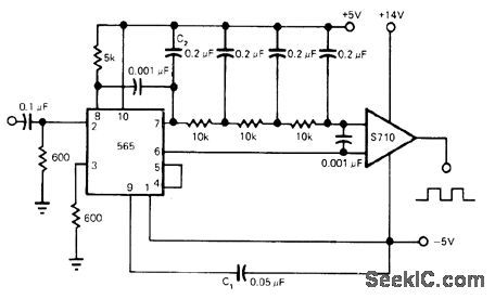
Developed for frequency-shift keying used in data transmission over wires, in which inputs vary carrier between two preset frequencies corresponding to low and high states of binary input signal. Circuit uses elaborate filter to separate modulated signal from carrier signal passed by PLL. 565 PLL provides reference for S710 comparator. Article gives design equations. -E. Murthi, Monolithic Phase-Locked Loops-Ana-logs Do All the Work of Digitals, and Much More, EDN Magazine, Sept. 5, 1977, p 59-64. (View)
View full Circuit Diagram | Comments | Reading(3712)
Published:2009/7/14 4:05:00 Author:May

Use of 555 timer as pulse-width-modulated regulator gives line regulation of 0.5% and load regulation of 1%. Circuit includes current foldback, With 15-V input, output is 10 V, -P. R. K. Chetty, Put a 555 Timer in Your Next Switching Regulator Design, EDN Magazine, Jan, 5, 1976, p 72. (View)
View full Circuit Diagram | Comments | Reading(622)
Published:2009/7/14 4:05:00 Author:May

Used to provide bandpass between 55 and 65.5 Mc for signal from 10-mmfd plate capacitance.-R. B. Hirsch, How to Design Band-pass Triples, Electronics, 32:34, p 41-44. 800-cps. (View)
View full Circuit Diagram | Comments | Reading(577)
Published:2009/7/14 4:04:00 Author:May


Fieldeffect transistor circuit (enclosed in dashed rectangle) serves as dropping resistor working into antiresonant a-f filter, to deliver constant voltage to filter despite input voltage variations. Uses 2N2386 fet as Q1.-H. H. Nord, the FET as a Voltage-Controlled Resistor, EEE, 13:1, p 65. (View)
View full Circuit Diagram | Comments | Reading(830)
Published:2009/7/15 4:39:00 Author:Jessie

Combines functions of rectangular pulse generator and width modulator for analog multiplier having error less than 2% of full-scale output-A. J. Ferraro, Multiplier for Analog Computers, Electronics, 33:45, p 73-74. (View)
View full Circuit Diagram | Comments | Reading(0)
Published:2009/7/14 4:04:00 Author:May

Uses conventional linear transformer in conventional bistable flip-flop to store information.-W. M. Carey, Using Inductive Control in Computer Circuits, Electronics, 32;38, p 31-33. (View)
View full Circuit Diagram | Comments | Reading(547)
Published:2009/7/14 4:03:00 Author:May

Combination of SCR and line relay gives faster action than circuit breaker for protection against current overload. Closing S1 momentarily energizes relay, completing current path from supply to load. Overload current increases voltage drop across R1 to above 0.65 v, switching on SCR and thereby shorting relay coil to make it open. S1 must be pressed again to reset relay. For adjustable dropout, gate of SCR can be connected to pot placed across R1.-R. Quong, Resettable Electronic Fuse Consists of SCR and Relay, Electronics, Sept. 15, 1977, p117. (View)
View full Circuit Diagram | Comments | Reading(2373)
Published:2009/7/14 4:03:00 Author:May
Both examples give at least 40 db attenuation below 2,740 cps when inserted between 600-ohm source and load resistances.-K. Lichtenfeld, Method for Simplifying Filter Design, Electronics, 33:21, p 96-99. (View)
View full Circuit Diagram | Comments | Reading(1296)
Published:2009/7/15 4:38:00 Author:Jessie

Electronic multiplication is achieved by making slope of sawtooth wave proportional to one factor and duration to other factor. Peak height of triangle will then be proportional to product. Triangle is generated by charging C with collector current of constant generator Q1 during time interval in which Q2 is cut off. -T. R. Hoffman, Analog Multiplication Using Time as One Variable, Electronics, 33:33, p 136-138. (View)
View full Circuit Diagram | Comments | Reading(804)
Published:2009/7/14 4:03:00 Author:May


Input counting rate is up to 70 Mc. Saturating transistor gale minimizes turnoff and turnon delay. Flip-flop transition is completed in less thon 16 mil-limicrosec.-High-Speed Switching Transistors (CBS Electronics ad), Electronics, 33:39, p 45. (View)
View full Circuit Diagram | Comments | Reading(739)
Published:2009/7/14 4:03:00 Author:May

Direct-reading RF wattmeter developed for use at 27.12 MHz is accurate to within 1% of full scale. Circuit can be adapted for other frequencies up to about 100 MHz. Does not require subtraction of two readings to find power transferred to mismatched loads. RF line current and voltage are sensed by current transformer and voltage divider that can be remotely located. Meter is driven by IC balanced mixer functioning as four-quadrant analog multiplier. Average product of voltage and current appears as DC reading on microammeter.-F. C. Gabriel,Compact RF Wattmeter Measures up to 50 Watts、Electronics, Nov. 8, 1973,p 122. (View)
View full Circuit Diagram | Comments | Reading(1192)
Published:2009/7/14 4:02:00 Author:May
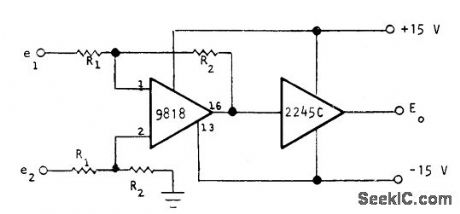
Optical Electronics 9818 opamp and 2245C logamp together give logarithm of differential input voltage or current. Combined transfer function is E0 = K log (R2 /R1 ) (e2- e1). R1 can be zero for differential input current circuit. For unity-gain preamp, R1 and R2 should be 10K. For 1-V full-scale Input, use 10K for R1 and 100K for R2, For l00-mV fullscale input, use 10K for R1 and 1 megohm for R2.- How to Obtain a Differential Logarithm, Optical Electronics, Tucson, AZ, Application Tip 10126. (View)
View full Circuit Diagram | Comments | Reading(592)
| Pages:635/2234 At 20621622623624625626627628629630631632633634635636637638639640Under 20 |
Response in 12 hours
© 2008-2012 SeekIC.com Corp.All Rights Reserved.