
Circuit Diagram
Index 633
1_WATT_FET_AUDIO_AMPUFIER
Published:2009/7/14 4:13:00 Author:May
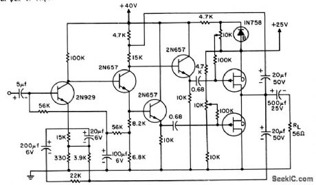
Voltage amplifier is followed by split-load phase inverter and push-pull output stage. Emitter-followers drive output stage to improve transistors, McGraw-Hill, N.Y., 1965, p 98. (View)
View full Circuit Diagram | Comments | Reading(826)
WIEN_BRIDGE_FILTER
Published:2009/7/14 4:13:00 Author:May

Does not have high Q but provides good rejection (40 db attenuation with 1 % tolerance components and 60 db with 0.1% tolerance components).-J. K. Goodwin, Wien Bridge Forms Rejection Filter, Electronics, 32:1, p 58-59. (View)
View full Circuit Diagram | Comments | Reading(0)
DYNAMIC_NOTCH_FILTER
Published:2009/7/14 4:12:00 Author:May

Will trap out 10-Mc noise while passing 10.Mc signal in heterodyne frequency convertor used to extend measurement range of 10-Mc counter. Operation is based on difference in level of noise and desired signal. Dynamic action of filter nulls out low-level noise, but filter disappears in presence of desired high-level signal. -H. T. McAleer, Dynamic Notch Filter, FEE, 10:9, p 90-91. (View)
View full Circuit Diagram | Comments | Reading(809)
SYNC_SEPARATOR
Published:2009/7/15 4:55:00 Author:Jessie

Input video having negative synchronizing pulses is applied to Q1 through 3.58-MHz notch filter Lt-Ct to remove color subcarrier components. Circuit is set up to conduct only on negative peaks, when Q1 Q2, and CR1 are all on, so feedback is 100% at this time. Negative peaks of output then follow input exactly. C2 acts as memory for negative peaks, storing their level between sync pulses.-W. Jung, An Operational Approach to Sync Separation, EDN/EEE Magazine, July 15, 1971, p 48-49. (View)
View full Circuit Diagram | Comments | Reading(0)
INDEPENDENT_ON_AND_OFF_PERIODS
Published:2009/7/15 4:55:00 Author:Jessie
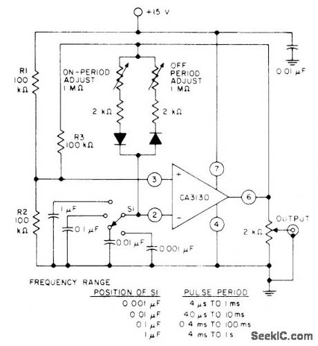
High input resistance of CA3130 opamp permits use of high RC ratios in timing circuits, to give pulse period range of 4 μs to 1 s with switch-selected capacitors.- Circuit Ideas for RCA Linear ICs, RCA Solid State Division, Somerville, NJ, 1977, p5. (View)
View full Circuit Diagram | Comments | Reading(683)
33_kW_SWITCHING
Published:2009/7/14 4:12:00 Author:May

Delco DTS-518 and DTS-519 power transistors in high-efficiency stacked supply are operated at 25-kHz switching rate to provide 330 VDC at 10 A. Control circuit operates at primary 50-kHz pulse frequency, with negative-going pulses having 2-μs duration. Flip-flop converts this to 25-kHz complementary square-wave signal driving Darlington DTS-2000s. Transformer cores are Magnetics EE No. 42510 each having 15-tum primary and 5-tum secondary for driving DTS-518s. Error amplifier compares portion of total output voltage to zener reference for control of DTS-519 power transistor switching at 25 kHz. Efficiency is 95% at full Ioad.- 3.3kW High Efficiency Switch Mode Regulator, Delco, Kokomo, IN, 1977, Application Note 59. (View)
View full Circuit Diagram | Comments | Reading(842)
SINGLE_SUPPLY_LINE_DRIVER
Published:2009/7/15 4:53:00 Author:Jessie

Motorola MC75451P driver and external components shown provide differential signal for twisted-pair transmission line from single +5 V supply. External gate provides required input phase reversal to gate G2 of IC. Each output ofIC varies between 0.5 V and 3.6 V, so net differential voltage driven into line is about 6 V. Only receiver end of line is terminated in its characteristic impedance, since arrangement is intended only for point-to-point transmission. -T. Hopkins, Line Driver and Receiver Considerations, Motorola, Phoenix, AZ, 1978, AN-708A, p 12. (View)
View full Circuit Diagram | Comments | Reading(724)
LATTICE_COUPLING_OF_DOUBLE_TUNED_FILTER
Published:2009/7/14 4:11:00 Author:May

Permits adjusting coupling between input and output resonant circuits to com pensate for stray reactances and variations in component values. Used in 30.Mc i-f amplifier requiring 1-Mc bandwidth. One side of variable capacitor is grounded, per mitting convenient mechanical design.-J. H. Grindon, Lattice Coupling of Resonant Circuits, EEE, 13:6, p 53-55. (View)
View full Circuit Diagram | Comments | Reading(649)
100_mA_CURRENT_REGULATOR
Published:2009/7/14 4:11:00 Author:May

Two-terminal circuit using LM195 power transistor has low temperature coefficient and operates down to 3 V. 2N2222 controls voltage across current-sensing resistor R2 and diode D1. Voltage across sense network is base-emitter voltage of 2N2222 plus 1.2 V from LM113. R1 sets current through LM113 to 0.6 mA. -R. Dobkin, Fast IC Power Transistor with Thermal Protection, National Semiconductor, Santa Clara, CA, 1974. AN-110, p6. (View)
View full Circuit Diagram | Comments | Reading(0)
PSEUDORANDOM_CMOS
Published:2009/7/15 4:53:00 Author:Jessie

Uses MC14021 8-bit shift register in conjunction with MC14507 EXCLUSIVE-OR gates to generate pseudorandom digital code. To develop code pattern, 1st, 6th, 7th, and 8th bits are sent through EXCLU-SIVE-OR gates and fed back to shift-register input. Output can be used as random test signal or for protecting messages sent over public channels or stored in public files. Digital message is scrambled by mixing it with output of code generator in EXCLUSIVE-OR gate. Functionally identical 255-bit random generator is used at receiver to unscramble data. Decoding circuit must have access to sending clock and means for synchronizing so as to put both registers into all-1 state. Register in receiver goes through all its states within 255 clock pulses; when it reaches all-1 state, signal is fed back to sender for releasing FF-1 so scrambling can commence. Article traces operation in detail. -J. Halligan, Pseudo-Random Number Generator Uses CMOS Logic, EDN Magazine, Aug. 15, 1972, p 42-43. (View)
View full Circuit Diagram | Comments | Reading(1328)
TWIN_T_400_CPS_FILTER
Published:2009/7/14 4:11:00 Author:May

Used with modulators lo increase signed-noise ratio. Filter is tuned to 400 cps, and eliminates other frequencies by feeding them back. Q of fiber is 6. Output is low-distortion sine wave in phase with input. Frequency regulation of cattier signal should be barter than 1% or liter will introduce phase shift.-L. S. Klivans, Modulators for Automatic Control Systems, Electronics, 31:1, p 82-84. (View)
View full Circuit Diagram | Comments | Reading(792)
CONTROL_CIRCUIT_CUTS_INVERTER_IDLINGCURRENT
Published:2009/7/15 4:52:00 Author:Jessie

Reduces standby current to less than1 ma. Sensing element is pair of back- to-back silicon diodes, D1 and D2. Used when a-c power must be available on demand at many remote outlets even though actually ; used only few hours a day.-D. W. R. McKinley, Inverter Control Circuit Saves Power, Electronics, 34:31, p 56. (View)
View full Circuit Diagram | Comments | Reading(675)
PHONO_PREAMP_1
Published:2009/7/14 4:11:00 Author:May
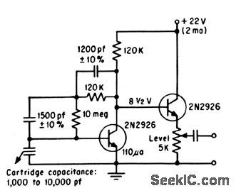


Two planar passivated silicon transistors give RIAA equalization for ceramic cartridge.-General Electric Co.(ad),Electronics, 37:17, p 38. (View)
View full Circuit Diagram | Comments | Reading(916)
WIRED_OR_TERMINALS
Published:2009/7/15 4:50:00 Author:Jessie

Arrangement permits connecting several IC line drivers in parallel for feeding single 100-ohm twisted-pair data line. With wired-OR transmitting capability, TTL output of receiver at right is logic 1 only if all paralleled drivers are transmitting logic 1. If any one or all of drivers transmit logic 0, output of receiver logic 0,-D, Pippenger, Termination Is the Key to Wired-OR Capability, EDN/EEE Magazine, Dec 15, 1971, p17. (View)
View full Circuit Diagram | Comments | Reading(637)
ACTIVE_800_CPS_PARALLEL_T_FILTER
Published:2009/7/14 4:10:00 Author:May

Potentiometer adjusts amount of rejection to compensate for tolerances of components. Second emitter-follower provides lower output impedance so feedback to network is more effective in sharpening notch of filter characteristic and in decreasing phase shift around null frequency. Used in servo sys terns.-T. Mollinga, Actiye Parallel-T Net.works, EEE, 14:4, p 93-98, (View)
View full Circuit Diagram | Comments | Reading(803)
DUAL_DETECTORS_PREVENT_LOCKING_ON_SIDEBANDS
Published:2009/7/15 4:49:00 Author:Jessie

Antisideband circuit rejects side-band locking while telemetry tracking loop is automatically searching for signals around i-f value. Circuit also provides both p-m and aim demodulation. Emitter-follower Q1, receiving i-f signal, feeds discriminator Q6-07 through limiters Q2-Q3 and Q4-05. For 455-kc input, d-c outputs of diode detectors cancel at hose of Q8. For lower or higher frequencies, difference voltage serves to apply antisideband error signal to loop fiber through Q9 or Q10.-W. H. Casson and C. C. Hall, New Phase-Tracking Demodulator Will Not Lock on Sidebands, Electronics, 36:6, p 52-55. (View)
View full Circuit Diagram | Comments | Reading(618)
40_METER_35_W_AMPLIFIER
Published:2009/7/14 4:10:00 Author:May
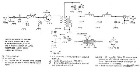
Designed for use with low-power(QRP)transmitter when band conditions are poor. Requires about 350-mW input. Half-wave filter at output keeps harmonics low Use heatsink for Q1.-T Mula, Codzila 1, QST, Feb. 1977, p14 – 15. (View)
View full Circuit Diagram | Comments | Reading(955)
V_F_CONVERTER
Published:2009/7/15 4:49:00 Author:Jessie

Can be used with any frequency counter. Only last three digits of display are read for voltage. VCO U22 runs at 1000 Hz when input is grounded and R3 is 56K. Counter is preset to 9000. For OV, count starts from 9000 and goes up to 10,000 on display, except that 1 at left overflows so reading is 0 V. If input is + 1 V, U22 goes upto 2000 Hz, appearing as 1000 on display. Voltage divider ahead of input is needed to divide full-scale voltages of 10, 100, and 1000 V down to basic 0-1 V range. Range switch is wired to place decimal in appropriate position. Use 2.7K for R2. DC voltages are in circles; upper value is for input probe of electronic voltmeter on +12 V, and lower value for input probe grounded. Terminal A goes to over range and reverse polarity indicators using 5558 dual opamp U23 and Archer (Radio Shack) 276-041 or equivalent LEDs. R4 and R5 depend on input-signal excursion range and exact value of sup-ply; start with 2700 ohms for R4 and 18K for R5.-J. Hall and C. Watts, Learning to Work with Integrated Circuits, QST, June 1976, p 20-24; revised circuit in June 1977, p 20-21. (View)
View full Circuit Diagram | Comments | Reading(1925)
20_W_SINGLE_ENDED_PUSH_PULL_OUTPUT
Published:2009/7/14 4:10:00 Author:May


Doubling number of output power tubes doubles ower output and halves loudspeaker impedance requirement. Separate cathode R-Cassembly for each pair of output tubes is recommended, but only one double choke isrequired. All pentodes are 6CW5.-J.Rodrigues De Miranda, Push-Pull Amplifiers DriveSpeaker Directly, Electronics, 31:29, p 76-79. (View)
View full Circuit Diagram | Comments | Reading(1443)
10_MHz_COAX_DRIVER
Published:2009/7/15 4:48:00 Author:Jessie

Provides high output current to coaxial line over bandwidth limited only by single-pole response of feedback components. Response is fiat with no peaking and distortion is low. Uses Harris HA-2530/2535 wideband amplifier having high slew rate.- Linear & Data Acquisition Products, Harris Semiconductor, Melbourne, FL, Vol, 1, 1977, p 7-54 (Application Note 516). (View)
View full Circuit Diagram | Comments | Reading(687)
| Pages:633/2234 At 20621622623624625626627628629630631632633634635636637638639640Under 20 |
Circuit Categories
power supply circuit
Amplifier Circuit
Basic Circuit
LED and Light Circuit
Sensor Circuit
Signal Processing
Electrical Equipment Circuit
Control Circuit
Remote Control Circuit
A/D-D/A Converter Circuit
Audio Circuit
Measuring and Test Circuit
Communication Circuit
Computer-Related Circuit
555 Circuit
Automotive Circuit
Repairing Circuit