
Circuit Diagram
Index 625
ONE_CHIP_THEREMIN_CIRCUIT
Published:2009/7/14 5:06:00 Author:May

Typically, a theremin uses two separate Colpitts LC oscillators, one of which can be slightly varied in frequency. The two frequencies are mixed together, and demodulated to reveal a beat frequency. If the two oscillators are at the same frequency, there is no beat or audio, but if they are off because of the proximity of your hand, a difference or beat frequency results, which is the audio output of the theremin. A 4011 quad gate, IC1, is the heart of this theremin. Taro gates are used for each of the two required oscillators running at 250 kHz. For the aerial, use a metal toilet-tank float. It provides much better sensitivity than a length of wire. The two RF signals are mixed, then amplified by IC2, an LM741 op amp. Audio is detected by D1, a 1N34 diode. Another LM741, IC3, is set up as an adjustable bandpass filter; still another LM741, IC4, further amplifies the audio for IC5, an LM386 audio amplifier. (View)
View full Circuit Diagram | Comments | Reading(2336)
24_V_AT_3_A_FOR_CATV
Published:2009/7/14 5:06:00 Author:May

Switching regulator design meets requirements for cable television systems where small size, low weight, and high efficiency are prime considerations. Circuit operates above 18 kHz either from 40-60 V 60-Hz square-wave source (CATV power line from ferroresonant transformer) or from DC standby source. Control circuit consists of dual apamp and linear IC timer used to vary ON time of 2N6546 power transistor. At start-up, Q4 is saturated and full input voltage is applied to primary of power transformer T1. Current then ramps up linearly until 04 is switched off by opamps Al and A2 and timer A3. Power transistor is operated between saturation and OFF state at above 18 kHz, with ON time varied while OFF time is fixed, to maintain constant output voltage as sensed by Al.-J. Nappe and N. Wellenstein, An 80-Watt Switching Regulator for CATV and Industrial Applications, Motorola, Phoenix, AZ, 1975, AN-752, p 5.
(View)
View full Circuit Diagram | Comments | Reading(1332)
AUTO_GENERATOR_REGULATOR
Published:2009/7/14 5:05:00 Author:May

Limits maximum generator current to safe value, pre vents current flow from battery through generator when generator voltage falls below battery voltage, and regulates voltage.-L. D. Clements, Solid-State Generator Regulator for Autos, Electronics, 33;8, p 52-54. (View)
View full Circuit Diagram | Comments | Reading(2517)
HIGH_VOLTAG_E_POSITIVE_SWITCHING
Published:2009/7/14 5:02:00 Author:May

Designed for operation from supply voltages above 40-V maximum rating of LM305 regulator. Output is +5 V at up to l0 A. Circuit uses fraction of input voltage as determined by R9 and zener, with Q2 providing voltage isolation between regulator and Unitrode PIC626 hybrid power switch.- Switching Regulator Design Guide, Unitrode, Watertown, MA, 1974, U-68A, p 9. (View)
View full Circuit Diagram | Comments | Reading(695)
OSCILLATOR_CONTROL
Published:2009/7/14 5:02:00 Author:May

Digitally controlled oscillator generates frequency proportional to integer output to 1408 DAC, for use as clock input of speed and direction control for bidirectional logic stepper motor serving as one output of microprocessor. Used to provide speed control for stepper. Number of bits determines number of speed selections available under computer control.-R.E. Bober, Taking the First Step, BYTE, Feb. 1978,p 35-36,38,102,104,106.and 108-112.
(View)
View full Circuit Diagram | Comments | Reading(0)
THEREMIN_CIRCUIT
Published:2009/7/14 5:01:00 Author:May

A theremin produces audio derived from mixing two high-frequency oscillators and using their audio-frequency difference as the note produced. Another oscillator is used to derive a volume-control signal, which varies the audio output level. Two or more oscillators are connected to short external rod or plate antenna electrodes; these are used as controls by bringing an object (one's hands) in proximity to them. By controlling hand movements, it is possible to create music or other sounds with this device.
(View)
View full Circuit Diagram | Comments | Reading(2320)
50_V_AT_1_kW
Published:2009/7/14 5:01:00 Author:May

Switching regulator operating at 10 kHz uses pulse-width modulation to give 87% efficiency at full load. Input voltage is 275 VDC. Inverter output drives combination of eight Delco 2N5157 power transistors connected in paralleled pairs in each leg of bridge circuit. Clamp diodes in each bridge leg prevent reverse conduction through collector-base diodes of transistors. Regulator consists of differential amplifier and two-stage DG amplifier controlling direct current through windings of magnetic amplifier.- One Kilowatt Regulated Power Converter with the 2N5157 Silicon Power Transistor, Delco, Kokomo, IN, 1972, Application Note 44, p 3. (View)
View full Circuit Diagram | Comments | Reading(867)
DIGITALLΥ__PROGRAMMED_INPUTS_AND_GAINS
Published:2009/7/14 4:59:00 Author:May

DG200 CMOS analog switch gives programmable choice of two inputs to opamp, and DG201 switch gives choice of four different gain values (1, 10, 100, or 1000) for opamp. Full opamp output range of ±12 V is provided even for unity-gain position of switch.-″Analog Switches and Their Applications,″ Siliconix, Santa Clara,CA,1976,p7-67. (View)
View full Circuit Diagram | Comments | Reading(557)
FSK_DEMODULATOR_WITH_CARRIER_DETECT
Published:2009/7/14 5:00:00 Author:May


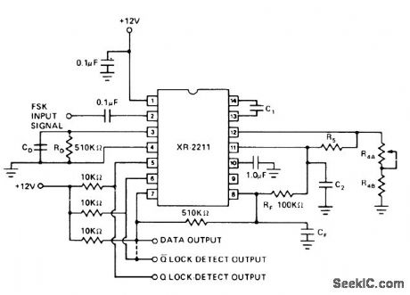
Exar XR-2211 FSK demodulator operating with PLL provides choice of outputs when carder is present; pin 5 goes low and pin 6 goes high when carrier is detected. With pins 6 and 7 connected, output from these pins provides data when FSK is applied but is low when no carrier is present. Circuit performance is independent of input signal strength over range of 2 mV to 3 VRMS. Center frequency is 1/C1R4 Hz, with values in farads and ohms. Choose frequency to fall midway between mark and space frequencies. Used in transmitting digital data over telecommunication I inks.- Phase-Locked Loop Data Book, Exar Integrated Systems, Sunnyvale, CA, 1978, p 57-61. (View)
View full Circuit Diagram | Comments | Reading(6326)
250_V_AT_3_A
Published:2009/7/14 4:52:00 Author:May

Single high-voltage silicon power transistor al serves as series element in switching regulator, with regulation obtained by pulse-width modulation. Delco DTS-431 pro-vides output of 250 V for maximum input of 325 V; other Delco transistors in same series give different combinations of output voltage and current in range of 300-750 W maximum output power. Efficiency is 92% at full load. Differential amplifier Q2-Q3 senses output voltage of regulator and feeds Schmitt trigger Q4-Q5 for turning series transistor al on and off. Resulting square wave of voltage is smoothed by LC filter between Q1 and load.- Pulse Width Modulated Switching Regulator, Delco, Kokomo, IN, 1972, Application Note 39, p 3. (View)
View full Circuit Diagram | Comments | Reading(640)
MODEM
Published:2009/7/14 4:51:00 Author:May

Developed as part of TV terminal for microprocessor, to permit communication over telephone line with time-sharing computer system. Uses Motorola MC14412 modem chip for full-duplex FSK modulation having originate frequencies of 1270 Hz for mark and 1070 Hz for space, with answer frequencies of 2225 Ha for mark and 2025 Hz for space. AY-5-1012 UART serves as parallel interface to microprocessor. Article covers operation, construction, testing, connection to telephone lines, and use of modem. -R. Lange, Build the S35 Modem, Kil-obaud, Nov. 1977, p 94-96. (View)
View full Circuit Diagram | Comments | Reading(1574)
SOLID_STATE_TESLA_COIL
Published:2009/7/14 4:51:00 Author:May

A TV flyback transformer can double as a low-power Tesla coil. The Tesla circuit consists of a pulse generator, a driver circuit, and a high-voltage transformer. Resistors R1 and R2 determine the time duration that the output at pin 3 is off, while R3 and R4 along with R1 and R2 determine the ON time. Inductor L1 and regulator IC2 provide a clean, stable power source for the timer. Transistor Q1 acts as a buffer. Resistor R6 determines the rise time based on the time constant developed by R6 and the inherent gate capacitance of Q3. Resistor R8 limits current so that excessive current will not damage T1's primary winding. Capacitor C5 absorbs some of the back EMF generated in T1's primary.The pulse waveform from IC1 is applied to Q1, which provides the high current necessary to offset the high capacitance of Q3. Capacitor C5 partially absorbs the primary EMF, reducing the stress on Q3. The spike produced in the secondary creates a ringing oscillation. When this oscillation begins to decay, Q3 is once again switched into its ON state. This dumps the energy into C5 and builds the magnetic field in T1. If the timing of both the ON and OFF states of the pulse train is adjusted correctly, the secondary of T1 produces a nearly constant, high-frequency, high-voltage current. (View)
View full Circuit Diagram | Comments | Reading(12803)
24_V_3_A_SWITCHING_MODE
Published:2009/7/14 4:50:00 Author:May

Circuit operates at 20 kHz from AC line with 70% efficiency. Control portion uses quad comparator and optoisolator and provides short-circuit protection. Logic drive uses push-pull transistors to switch 2N6306 power transistor at 20-kHz rate. Load regulation is 0.8% over output range of 1.5 to 3 A with 120-VAC input. Line regulation is 3% at 3 A for input range of 100 to 140 VAC.-R. J. Haver, “A New Approach to Switching Regulators.” Motorola, Phoenix, AZ, 1975, AN-719, p 11. (View)
View full Circuit Diagram | Comments | Reading(765)
CONSTANT_CURRENT_SUPPLY
Published:2009/7/14 4:48:00 Author:May

Used to measure resistivity of semiconductors rapidly and accurately. Switch gives choice of 0.5, 5, and 50 ma. Values are read from dial settings rather than meters, to increase accuracy-P. J. Olshefski, Constant. Current Generator Measures Semiconductor Resistance, Electronics, 34:47, p63. (View)
View full Circuit Diagram | Comments | Reading(770)
TESLA_COIL
Published:2009/7/14 4:47:00 Author:May

The traditional Tesla coil is connected as shown. The primary capacitor, an HV ac type, typically 500 to 5000 pF, and the inductance of the primary winding should resonate around the resonant frequency of the secondary coil. (View)
View full Circuit Diagram | Comments | Reading(0)
_5_V_SWITCHING_AT_10_A
Published:2009/7/14 4:47:00 Author:May

Unitrode PIC625 hybrid power switch provides switching action for LM305 regulator at switching speeds up to 100 kHz for input voltage range of 20-40 V. Circuit operates in fixed OFF-time mode that makes output ripple independent of input voltage. Q1 provides current-limiting action.- Switching Regulator Design Guide, Unitrode, Watertown, MA, 1974, U-68A, p 7. (View)
View full Circuit Diagram | Comments | Reading(1720)
103_COMPATIBLE_MODEM
Published:2009/7/14 4:46:00 Author:May

Motorola 4412IC converts serial data, usually to and from uni-versal asynchronous receiver-transmitter, into tones suitable for telephone communication. In originate mode, logic0 is transmitted as 1070 Hz and logic 1 as 1270 Hz. In answer mode, logic 0 is transmitted as 2025 Hz and logic 1 as 2225Hz. Modems are used in pairs, with receiver responding to tone group not being transmitted. Speed capability is up to 300-baud data rate. Output is 300 mVRMS into 100k load.-D. Lan-caster, CMOS Cookbook, Howard W. Sams, Indianapolis, IN, 1977, p 133. (View)
View full Circuit Diagram | Comments | Reading(694)
MULTIPLE_OUTPUT_SWITCHING_REGULA_TOR
Published:2009/7/14 4:45:00 Author:May

Additional output are obtained from switching regulator by adding secondary windings to power transformer. Motorola MC3380 astable MVBR serves as control element. Feedback is achieved by amplifying output error with opamp A1 and applying this voltage to pin 6. Report covers design of transformer and power circuit.-H. Wurzburg, Control Your Switching Regulator with the MC3380 Astable Multivibrator, Motorola, Phoenix, AZ, 1975, EB-52. (View)
View full Circuit Diagram | Comments | Reading(889)
TEMPERATURE_COMPENSATED_MILLIVOLT_REFERENCE
Published:2009/7/14 4:44:00 Author:May

Two identical diodes are used to derive a temperature -compensated voltage across R2. Select two diodes of the same manufacture with, for example, 10-mV difference in forward drop at the same current. Then the output will be compensated because both diodes will very likely have the same temperature coefficient (they are of identical manufacture). (View)
View full Circuit Diagram | Comments | Reading(996)
TEMPERATURE_COMPENSATED_CURRENT_SOURCE
Published:2009/7/14 4:44:00 Author:May

Presents 1,000 meg of output impedance while supplying up to 200 no of temperature-compensated current. Germanium diodes serve as compensating network drawing 1.3 ma. Based on fact that matched transistor pairs have base-current temperature coefficients that are predictable as function of operating current-C. C. Hanson, Low. Drift Current Generator Compensates for Temperature, Electronics, 39:12, p 108-109. (View)
View full Circuit Diagram | Comments | Reading(760)
| Pages:625/2234 At 20621622623624625626627628629630631632633634635636637638639640Under 20 |
Circuit Categories
power supply circuit
Amplifier Circuit
Basic Circuit
LED and Light Circuit
Sensor Circuit
Signal Processing
Electrical Equipment Circuit
Control Circuit
Remote Control Circuit
A/D-D/A Converter Circuit
Audio Circuit
Measuring and Test Circuit
Communication Circuit
Computer-Related Circuit
555 Circuit
Automotive Circuit
Repairing Circuit