
Circuit Diagram
Index 497
Temperature compensation circuit with the thermistor
Published:2011/8/24 21:30:00 Author:Christina | Keyword: Temperature, compensation, thermistor
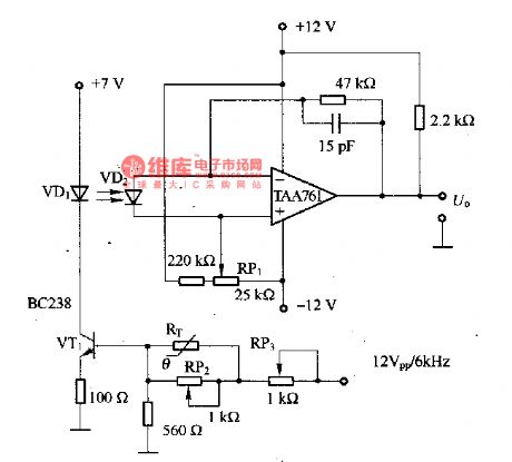
The temperature compensation circuit with the thermistor is as shown in the figure. It is designed as the temperature-compensation circuit of the infrared light-emitting diode VD1, the VD1 can be used as the photodetector of the modulated light, the maximum current is 50mA, the temperature range is 10-55℃. RT can be used as the thermistor with the negative temperature coefficient, and it is connected with the base of VT1 to reduce the self-heating effect of the thermistor. The RP2 and RP3 can be used to adjust the temperature compensation feature. VD2 is the receiver that can amplify the receiving signal through the TAA761.
(View)
View full Circuit Diagram | Comments | Reading(1650)
AN5836 audio preamplifier and control integrated circuit
Published:2011/9/8 19:58:00 Author:Christina | Keyword: audio preamplifier, control, integrated circuit

The AN5836 is designed as the audio preamplifier and control integrated circuit that is produced by the Panasonic company, and it can be used in the TV sound system and home theater system.
1.The typical application circuit of the AN5836
The typical application circuit of the AN5836 is as shown in figure 1.
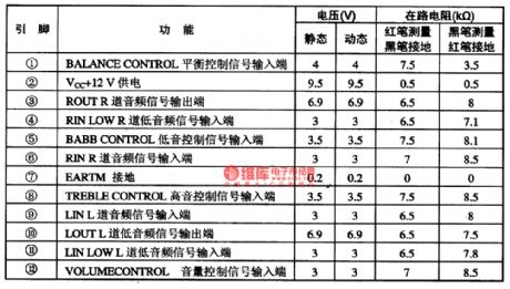
2.The pin functions and data of the AN5836
The AN5836 uses the single row 12-pin package, the pin functions and data are as shown in table 2.
3. The working process of the circuit
The L-IN and R-IN signals are input from the pin-9 and pin-6 of the AN5836 circuit, and the signals are adjusted by the AN5836, then they are output by pin-3 and pin-4. (View)
View full Circuit Diagram | Comments | Reading(4107)
Infrared control automatic faucet composed of the NE555 and LM567
Published:2011/9/8 19:58:00 Author:Christina | Keyword: Infrared control, automatic, faucet

The infrared control automatic faucet has the same control principle with the infrared control automatic hand dryer. The infrared control automatic hand dryer is used to control the on and off of the electric blower, but the infrared control automatic faucet is used to control the on and off of the electromagnetic water valve. Here I introduce the infrared control automatic faucet, the composition is as shown in the figure. This circuit is composed of the infrared transmitter, the infrared receiver amplifier and the valve switch controller.
(View)
View full Circuit Diagram | Comments | Reading(2259)
S1-3090C Controllable Voltage Regulator Circuit Diagram
Published:2011/9/3 21:34:00 Author:Zoey | Keyword: Controllable, Voltage Regulator
As a controllable voltage regulator integrated circuit, S1-3090C is widely used in audios, DVD players and so on. 1 Features S1-3090C IC consists of a+9 V voltage regulator circuit, a power on / off control circuit, and other auxiliary function circuits. 2 Pin functions and data S1- 3090C adopts pin-4single integrated circuit package,whichhasbeen used in Fine Refine King rear projection TVs,itspin functions of the integrated circuit and relevant data have been listed in Table 1.
(View)
View full Circuit Diagram | Comments | Reading(679)
SID2141X Video Preamplified Circuit Diagram
Published:2011/9/3 21:28:00 Author:Zoey | Keyword: Video Preamplified
SID2141X is a kind of video preamplifier ICand it iswidely used in a variety of domestic and imported color monitors. The SD2141X integrated circuit contains a three-color signal processing circuit, a three-color gain control circuit, and ablanking signal processing circuit,tec. Thecircuit uses20-pin dual in-line package, and the circuits have been used in LGCB56lBN color monitors,its foot arch function and dataof the integrated circuit have been listed in Table 1. (View)
View full Circuit Diagram | Comments | Reading(884)
AN5743 audio preamplifier and power amplifier integrated circuit
Published:2011/9/8 19:59:00 Author:Christina | Keyword: audio preamplifier, power amplifier, integrated circuit


The AN5743 is designed as the audio preamplifier and power amplifier integrated circuit which is produced by the Panasonic company, and it can be used in all kinds of stereo systems.
1.The internal circuit block diagram and the functions of pin-5
The internal circuit of the AN5743 has the audio preamplifier, audio incentive and power amplifier functions. Also this circuit has the features of less external components, simple circuit structure. The internal circuit block diagram and the typical application circuit are as shown in figure 1-20. This IC uses the single row 9-pin package, the integrated circuit and data are as shown in table 1-21.
2.The typical application circuit of the AN5743
The typical application circuit of the AN5743 is as shown in figure 1-20.
3.Operating process (View)
View full Circuit Diagram | Comments | Reading(1209)
The FM circuit with the transfiguration diode
Published:2011/8/24 21:34:00 Author:Christina | Keyword: FM, transfiguration diode
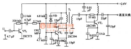
The FM circuit with the transfiguration diode is as shown in the figure. In this circuit, the VT1 changes the signal Ui which is produced by the electret condenser microphone into the operating voltage of the varactor diode VD. The LC oscillator circuit which is composed of the VT2 produces the 80MHz band signal. We can use the varactor diode VD to change the frequency of the resonant circuit, so we do the frequency modulation directly. When the output Vi is 3mV, the modulation frequency is +/-25khz. The VT3 is the high-frequency amplifier, it amplifies the modulated signal to 2.3mV and delivers it to the antenna.
(View)
View full Circuit Diagram | Comments | Reading(774)
Temperature measurement circuit composed of the K-type thermocouple
Published:2011/9/8 19:59:00 Author:Christina | Keyword: Temperature measurement circuit, K-type, thermocouple

The temperature measurement circuit composed of the K-type thermocouple is as shown in the figure. In the temperature range of -40-500°F, the thermoelectric potential of the K-type thermocouple and the temperature has a good linear relationship, the relationship can be expressed as UY=0.226TX-0.707. In the formula, the UY is the thermoelectric potential (mV), the Tx is the temperature (°F). Tx=(UY十0.707)/0.226=(1OlUY十71.4)/22.8°F, so we get the 1mV/°F output. In the circuit, the LTl025 produces the cold contact point compensation voltage of the thermocouple, A1 amplifies the thermocouple output for 101 times, the stable voltage of WD1 is adjusted to 71.4mV by RP1, and it adds to the reverse phase input port of the addition amplifier.
(View)
View full Circuit Diagram | Comments | Reading(2980)
Double-channel infrared remote control switch (LM567, CD4013)
Published:2011/9/8 19:59:00 Author:Christina | Keyword: Double-channel, infrared, remote control, switch
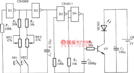
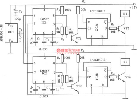
The double-channel infrared remote control switch which is as shown in the figure changes the channel control signal into the high frequency carrier frequency signal by modulating the carrier frequency signal, and it outputs the signal through the infrared transmitting tube. This kind of control mode is very helpful to resist the interference, it makes the remote control circuit more reliable, the structure of it is as shown in the figure. This circuit is composed of the double-channel infrared transmitter, the infrared receiver modem, the channel selector and the switch controller.
The emitter:
The receiver:
(View)
View full Circuit Diagram | Comments | Reading(4820)
Infrared remote control delay power saving switch composed of the CX20106 and NE555
Published:2011/9/8 20:00:00 Author:Christina | Keyword: Infrared, remote control, delay, power saving, switch

The circuit is composed of the special infrared receiving demodulation integrated circuit CX20L06 and the NE555 circuit, this circuit uses the two-way thyristor as the switch of the light. It is the fully integrated infrared remote control switch circuit, the structure is as shown in the figure.
(View)
View full Circuit Diagram | Comments | Reading(1470)
The application circuit of the AN6701
Published:2011/8/24 21:34:00 Author:Christina | Keyword: application circuit
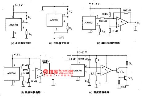
The application circuit of the AN6701 is as shown in the figure. The AN6701 has the features of high sensitivity, the cheaper price, the wide operating temperature range. The main characteristic parameters of it: the temperature range is -10 to +80℃; the sensitivity (Rc=1-100kΩ) is 105-113mV/℃, the nonlinearity is +/-0.5%; the thermal time constant in the still air is 24S, in the wind air is 11S; in the still air, the thermal resistance is 300℃. The output voltage of the sensor (25℃) can be set to 5.0V by the external resistor. The AN6701 is composed of the temperature-sensitive component, the temperature compensation component and the amplifier, it outputs the low impedance. It uses the miniature package to improve the thermal response characteristics.
(View)
View full Circuit Diagram | Comments | Reading(595)
DTMF coding multiple-channel infrared remote control switch circuit
Published:2011/9/8 20:01:00 Author:Christina | Keyword: DTMF, coding, multiple-channel, infrared, remote control, switch
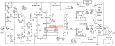
The DTMF codec is the abbreviation of the dual-tone multi-frequency codec. The multiple-channel infrared remote control switch circuit which is composed of the DTMF is as shown in the figure. It is composed of the infrared remote control signal emitter, the infrared receiving signal amplifier, the DTMF signal decoder, the 12-channel data decoding distributor and the circuit switch controller.
(View)
View full Circuit Diagram | Comments | Reading(3683)
The regulator: DC-DC circuit, power supply monitor pin and main features LM2940
Published:2011/8/30 2:23:00 Author:Seven | Keyword: DC-DC circuit, power supply, monitor pin
LM2940 serial low voltage gap 3-terminal stabilizer (forward output) This is a low voltage gap 5-terminal stabilizer whose output voltage is stable; its output voltages are 5V, 8V and 10V; output current is 1A; output current is 1A; minimum input-output voltage gap is low than 0.8V; maximum input voltage is 26V; working temperature is -40~+125℃; it contains the static current step-down circuit, current protection, over-heat protection, battery inversed grafting and inversed inverting protection circuit. The approaching type is W2940.
(View)
View full Circuit Diagram | Comments | Reading(655)
The regulator: DC-DC circuit, power supply monitor pin and its main features LM330
Published:2011/8/30 2:23:00 Author:Seven | Keyword: DC-DC circuit, power supply, monitor pin

LM330--3-terminal stabilizer(positive output) This is a 3-terminal stabilizer with fixed output voltage; the output voltage is 5V; output current is 150mA; output voltage fault is ±5%; when the output current is 150mA, the minimum input-output voltage is lower than 0.6V; the max input voltage is 26V; the working temperature is 0~+70 ℃; it contains the current limitation, overheat protection, batter reverse connection inserting and inverting inserting and input transition state protection circuit.
(View)
View full Circuit Diagram | Comments | Reading(698)
The regulator: DC-DC circuit, power supply monitor pin and its main features LM342
Published:2011/8/30 2:23:00 Author:Seven | Keyword: DC-DC circuit, power supply, monitor pin

The 3-terminal regulator (forward output) of LM342 series This is a 3-terminal regulator of fixed output voltage; its output voltages are 5V, 12V and 15V; its output current is 250mA; its output voltage difference is ±5%; when the output voltage is 5V, the max input voltages are 30V; when it is 12V or 15V, the max input voltage is 35V; its working temperature is 0~+70℃; it contains the current limitation, over-heat break-down and secure working area protection circuit.
(View)
View full Circuit Diagram | Comments | Reading(804)
The regulator: DC-DC circuit, power supply monitor pin and its main features LM368-25
Published:2011/8/30 2:22:00 Author:Seven | Keyword: DC-DC circuit, power supply, monitor pin

LM368-2.5 reference voltage circuit (+2.5V) This is a high-precision, low temperature drift and low-noise 3-terminal Vref circuit; its output voltage is 2.5V, which can be micro-adjusted by ADJ; its max input voltage fault is ±0.2%; the maximum input stability is 0.0005%/mA; its max temperature drift is 11*10-6/℃; its max output stability is 0.0025%/mA; it max output voltage is 35V; its power consumption is 600mW; its working temperature is 0~+70℃; it contains the output short circuit protection circuit.
(View)
View full Circuit Diagram | Comments | Reading(998)
The regulator: DC-DC circuit, power supply monitor pin and its main features LM3999
Published:2011/8/30 2:22:00 Author:Seven | Keyword: DC-DC circuit, power supply, monitor pin

LM3999reference voltage circuitThis is a high-precision, low temperature drift and low-noise 3-terminal Vref circuit; its output voltage is 6.95V; temperature drift is 0.0005%/℃; output voltage fault is ±5%; working current range is 0.5~10mA; the typical value of its working impedance is 0.5Ω; the long-term time stability is 20*10-6/1000h; the maximum reversed current is 20mA; the maximum forward current is 0.1mA; its working temperature is 0~+70℃; it contains the temperature compensation.
(View)
View full Circuit Diagram | Comments | Reading(735)
The regulator: DC-DC circuit, power supply monitor pin and its main features LMC7660/7669
Published:2011/8/30 2:21:00 Author:Seven | Keyword: DC-DC circuit, power supply, monitor pin

LMC7660/7669 CMOS voltage converterThis is a CMOS voltage converter generating the negative output whose voltage is equal to the positive output; it working voltage range is 1.5~10V; the max static current of LMC7660 is 200μA; the power converting efficiency is 95%; the power consumption of the pottery sealing is 0.9W; the working temperature is the pottery sealing is -55~+125℃, the plastic package is -40~+85%; it can work in the full temperature range and full voltage range.
(View)
View full Circuit Diagram | Comments | Reading(1075)
The regulator: DC-DC circuit, power supply monitor pin and its main features LM2930
Published:2011/8/30 2:24:00 Author:Seven | Keyword: DC-DC circuit, power supply, monitor pin

This is a low voltage gap 5-terminal regulator whose output voltage is stable; the output voltages are 5V and 8V; output current is 150mA; output voltage fault is ±2%; when the output current is 150mA, the minimum input-output voltage gap is low than 0.6V; the maximum input voltage is 26V; the working temperature is -40~85℃; it contains the current limitation, overheat protection, battery reversed polarity inserting, 40V input cutting-off and other functions. The approaching modes are LM2930T, LM2930KC, LM2930A and W2930.
(View)
View full Circuit Diagram | Comments | Reading(836)
The regulator: DC-DC circuit, power supply monitor pin and its main features LM2925
Published:2011/8/30 2:26:00 Author:Seven | Keyword: DC-DC circuit, power supply, monitor pin
LM2925-the 5V regulator (reset terminal) This is a low voltage gap 5-terminal regulator whose output voltage is stable; the output voltage is 5V; the maximum output current is 750mA; when the output is 500mA, the minimum input-output voltage gap is lower than 0.6V; when the output voltage is dropping, it is outputting a low but effective reset signal; the delaying time of the resetting signal output can be set by the external capacitors; the max input voltage is 26V; working temperature -40~+125℃; it contains functions of the current limitation, overheat protection, inverting inserting, 60V severing input and -50V transition state.
(View)
View full Circuit Diagram | Comments | Reading(690)
| Pages:497/2234 At 20481482483484485486487488489490491492493494495496497498499500Under 20 |
Circuit Categories
power supply circuit
Amplifier Circuit
Basic Circuit
LED and Light Circuit
Sensor Circuit
Signal Processing
Electrical Equipment Circuit
Control Circuit
Remote Control Circuit
A/D-D/A Converter Circuit
Audio Circuit
Measuring and Test Circuit
Communication Circuit
Computer-Related Circuit
555 Circuit
Automotive Circuit
Repairing Circuit