
Circuit Diagram
Index 488
Photo Couple Reversible Counting Display Circuit
Published:2011/9/8 1:49:00 Author:Sue | Keyword: Photo Couple, Reversible, Counting Display

The photo couple reversible counting display circuit uses photo couple devices as reversible counter which is made of optical sensor. It can count the devices with different operating direction by addition or substraction automatically. As seen in the figure, it is suitable to count the automatical continuous producted devices. In the circuit, the photo couple device is reflecting photo coupler. Infrared LEDs and photosensitive triode are connected at the angle of 35°, and the intersection point is 5mm from the photo coupler. When it is working, if the infrared LED's infrared ray is blocked by the thing forward, the infrared ray will be reflected back and be received by the photosensitive triode which will make the photosensitive triode connected. (View)
View full Circuit Diagram | Comments | Reading(1234)
10MHz Band-Pass Filter Composed of OPA603
Published:2011/9/11 20:29:00 Author:Felicity | Keyword: 10MHz, Band-Pass, Filter

The circuit makes use of the Broadband Features high-speed current feedback op amp (G=1~10, the broadband reaches 100MHz). It makes the 10MHz pass filter. The parameter is showed in picture. (View)
View full Circuit Diagram | Comments | Reading(1260)
The remote temperature measurement circuit composed of intelligent temperature sensor and external buffer
Published:2011/9/10 22:01:00 Author:Felicity | Keyword: remote temperature measurement circuit, intelligent temperature sensor, external buffer

During the remote temperature measurement, TMP03/04 has a big advantage over analog output temperature sensor. It’s becausethe output is digital signal which has a better performance of resisting disturbance. The proportion of T1/T2 cannot be affected between long distance transmission and an AD485 type RS-485 differential line drive can be added if necessary as shown in the circuit diagram. This circuit can transmit temperature signal over 1200m. The time delay caused by emitter and receiver in ADM485 is 5ns and won’t affect T1, T2. (View)
View full Circuit Diagram | Comments | Reading(893)
Telephone Recorder(CD4511B,CD4518B)
Published:2011/9/8 1:49:00 Author:Sue | Keyword: Telephone Recorder

The picture shows the telephone recorder. It is mainly used to record and display the number of use times of the telephone so that the user can know more about the condition of service of the telephone. The recorder consists of two 7-segment digital tubes so the highest counting can be 99. The circuit has the reset button so it can reset the counting. (View)
View full Circuit Diagram | Comments | Reading(1704)
Temperatur/Frequency conversion circuit ( low power programmable integrated temperature controller TMP01)
Published:2011/9/10 22:00:00 Author:Felicity | Keyword: Temperatur/Frequency conversion circuit, low power, programmable , integrated temperature controller

During long distance transmission, temperature signal can be converted into frequency signal and the circuit is shown in the figure. The AD654 voltage/frequency convertor (VFC for short) is adopted in the circuit which can suppress the noise disturbance and voltage fluctuation. When the precision of U/f conversion is enough, the output signal can stand for the test temperature which determined as follow. And CT is the capacity of the external timing capacitor of the internal oscillator. The frequency can be corrected by adjusting R5.
(View)
View full Circuit Diagram | Comments | Reading(1126)
Audio Display Circuit Composed of CD4017
Published:2011/9/8 1:50:00 Author:Sue | Keyword: Audio Display

The picture shows the audio display circuit. It uses left and right stereo sound channels to control the display matrix which is composed of LED. Then the display matrix will jitter according to the audio signal's rhythm. The circuit consists of amplifier, counter and display circuit. (View)
View full Circuit Diagram | Comments | Reading(3645)
Parallel output digital temperature transmitter circuit (integrated temperature sensor with voltage output LM35)
Published:2011/9/10 21:59:00 Author:Felicity | Keyword: Parallel output, digital temperature transmitter , integrated temperature sensor, voltage output

View full Circuit Diagram | Comments | Reading(1496)
Serial output digital temperature transmitter circuit (integrated temperature sensor with voltage output LM35)
Published:2011/9/10 22:01:00 Author:Felicity | Keyword: Serial output, digital temperature transmitter , integrated temperature sensor, voltage output

The output of LM35 is analog quantity and can get digital quantity output by A/D converter (ADC). A serial output digital temperature transmitter circuit with ADC08031 is shown in the figure and the range is +128℃ .The CLK and ENA in the figure are Clock terminal and Enable terminal.
(View)
View full Circuit Diagram | Comments | Reading(1601)
Output adapter circuit of LM35 series temperature sensor---- High precision 100 fields LED bar diagram display meter circuit
Published:2011/9/10 22:01:00 Author:Felicity | Keyword: temperature sensor, Output adapter circuit , High precision , 100 fields LED bar diagram display


High precision 100 fields LED bar diagram display meter circuit is shown. This meter adapts the output circuit of LM35 series temperature sensor. For example, to build up a 0~10oC thermometer , the division value can be 0.1℃. The circuit contains CH261 and LM3914. The work program of LM3914: (View)
View full Circuit Diagram | Comments | Reading(1836)
Average temperature measurement circuit composed of AD590(accurate integrated temperature sensor with current output)
Published:2011/9/10 22:03:00 Author:Felicity | Keyword: Average temperature measurement circuit, current output, accurate integrated temperature sensor


The figure shows the average temperature measurement circuit composed of AD590.The current through R is:.and the indication of the 1.0 millvoltmeter is the average temperature:i.e.Generally, assumed that the number test point is n and then the average temperature is:
(View)
View full Circuit Diagram | Comments | Reading(1273)
High-frequency Voltage Control Oscillator Circuit Composed of Transistor
Published:2011/9/8 1:49:00 Author:Sue | Keyword: High-frequency, Voltage Control, Oscillator, Transistor


The circuit shows the high-frequency voltage control oscillator circuit composed of transistor. In figure(a), C2 and C3 provide VT1's emitter and base electrode with positive feedback.The oscillation frequency's reactance set value is low, which is about a resistance value of hundreds of ohm, and the goal is to prevent VT1 parameter's change from influencing the resonance oscillation circuit. The resonance oscillation frequency will vary as L1 and variode VC1's capacitance vary. The oscillation output impedance conversion through C4, which can prevent it from being influenced by load variation.
In figure (b), L1's value can be determined by empirical method according to the oscillation frequency. (View)
View full Circuit Diagram | Comments | Reading(938)
Charge Display Circuit Composed of TB1004
Published:2011/9/8 1:50:00 Author:Sue | Keyword: Charge Display

The charge display circuit is mainly used to charge nickel-cadmium cell. When cell is charged, it uses LED to indicate the charging state. When it is charged, the LED is not illuminated, and it indicates that it is being charged. When the charging is finished, the LED is not illuminated, and it indicates that the charging is finished. According to different states of the LEDs, the user can know the charging states better. The picture shows the charge display circuit which is composed of TB1004. (View)
View full Circuit Diagram | Comments | Reading(578)
Active Biquadratic Band-pass Filter Circuit
Published:2011/9/8 1:51:00 Author:Sue | Keyword: Active, Biquadratic, Band-pass, Filter

For all the active filter circuits, the center frequency is 1KHz, the quality factor Q=50, and the gain Kv=100(equal to 40dB). (View)
View full Circuit Diagram | Comments | Reading(839)
Staff Approaching Detector(LM385)
Published:2011/9/8 1:51:00 Author:Sue | Keyword: Staff Approaching Detector

The picture shows the staff approaching detector circuit. The circuit uses ordinary photoelectric tube to detect the environmental light change caused by staff who go into the warning region, so that the detection function can be realised. (View)
View full Circuit Diagram | Comments | Reading(884)
Inductive Test Pencil(CD4069)
Published:2011/9/8 1:34:00 Author:Sue | Keyword: Inductive, Test Pencil

The picture shows the inductive test pencil. Its sensitivity is higher than common test pencil's sensitivity and it can test the wire's electrical property which the common test pencil can't do. IC1 is six phase inverter integrated circuit CD4069. Its inverter IC1-1 and the devices around will constitute a voltage amplifier with a high input impedance and a high gain. After the probe receives weak field signal, it is amplified and output by the amplifier and is transformed by phase-inverter IC1-2. Then it will controls the late grade circuit. The phase-inverter IC1-5,IC1-6 and resistor R5 and capacitor C2 will constitute multivibrator. Its work is controlled by the inverter IC1-3's working state. (View)
View full Circuit Diagram | Comments | Reading(1303)
Close-range Infrared Detection Circuit Composed of 555
Published:2011/9/8 1:52:00 Author:Sue | Keyword: Close-range, Infrared Detection

The figure (a) shows the close-range infrared detection circuit principle. The circuit realises detection of the controlled one by infrared ray close-range emitting and receiving. It can be used to realise close-range automatic instant control, such as bus's automatic door open/close control, washroom hand dryer's blowing control. The circuit consists of two parts: infrared ray emitting circuit and infrared ray receiving circuit. (View)
View full Circuit Diagram | Comments | Reading(1781)
camera electronic metering system
Published:2011/9/6 23:34:00 Author:chopper | Keyword: camera, electronic metering system
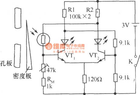
In the midrange camera, CdSphotosensitive resistor is taken as electronic metering device. Light is on the CdSphotosensitive resistorthrough the orifice, and you can move thedensity plate, so that the circuit will achieve a balance, and then two LEDs will light evenly to express the proper exposure.If only onelights while the other does not, it is due to underexposure or over exposure, then moving the density board can achieve the correct exposure purpose.The thermistor RM in the circuit(1kΩ) has temperature compensation function, to compensate error for temperature changes caused by photosensitive resistor. (View)
View full Circuit Diagram | Comments | Reading(1464)
Anti-inductive Crystal Oscillation Circuit
Published:2011/9/8 1:52:00 Author:Sue | Keyword: Anti-inductive, Crystal Oscillation Circuit

The picture shows the anti-inductive crystal oscillation circuit. In the circuit, C2 and C3 are positive feedback capacitor. The lower the frequency is, the larger the capacitance is. When the capacitance is 100pF, the oscillation frequency is 5-20MHz; C1 and C5 can be used to realise frequency fine tuning;VT2 is buffer circuit which can be used to prevent the frequency from changing while the load is changing; R1 and R2 are stablized resistor which can prevent emitter follower from oscillating abnormally. (View)
View full Circuit Diagram | Comments | Reading(604)
timing battery-conserving switch
Published:2011/9/6 23:34:00 Author:chopper | Keyword: timing, battery-conserving switch
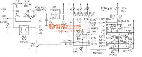
Door lamp isusually controlled by hands,which may make some waste of electrical energy and inconvenience if someone forgets to turn on or turn off.If it can increase light control and timing functions,it can achieve automation and energy-saving effect.The ready-made light-controlled timing ICMG2001B is a cheap 1h-36h,nine-gear optional timing,delay IC,and its peripheral circuit is simple ,and it is with driver of indicator light as well as interface of photoresistor.It adopts cheap 32.768kHz crystal as clock source whose order of accuracy will reach one over one hundred thousand.So it is suitable for automatical control circuit of street lamp. (View)
View full Circuit Diagram | Comments | Reading(1332)
Metal Detector(MC14046B)
Published:2011/9/8 1:52:00 Author:Sue | Keyword: Metal Detector

The picture shows the metal detector circuit. The detecting coil constitutes LC oscillating circuit. When the coil approaches the metal, the metal will have vortex inside which will make coil have varied inductance and the oscillating frequency of detector circuit will be changed accordingly. Figure (a) is the detector's functional block diagram. Figure (b) is the detecting circuit. (View)
View full Circuit Diagram | Comments | Reading(5057)
| Pages:488/2234 At 20481482483484485486487488489490491492493494495496497498499500Under 20 |
Circuit Categories
power supply circuit
Amplifier Circuit
Basic Circuit
LED and Light Circuit
Sensor Circuit
Signal Processing
Electrical Equipment Circuit
Control Circuit
Remote Control Circuit
A/D-D/A Converter Circuit
Audio Circuit
Measuring and Test Circuit
Communication Circuit
Computer-Related Circuit
555 Circuit
Automotive Circuit
Repairing Circuit