
Circuit Diagram
Index 491
ISPl362 and USB Host Interface Circuit
Published:2011/8/25 22:51:00 Author:Michel | Keyword: Host Interface Circuit

CC1020 signal sending and receiving interface and micro-controller connects are shown as the picture 1.Micro controller uses pins P2.6 , bidirectional synchronous data interface DIO, DCLK connection of P3.4 ,CC1020.
The two-way pins of micro-controller isconnected withCC1020 DIO.And it is used to emit and receive data (input and output). DCLK must be connected to an input terminalofthe micro-controller when it provides data.
Data output can choose to use separate pins. At this time to the register ,SEP_DI_DO=1 of CC1020 INTERFACE needs beset up.In synchronous mode, LOCK pins are used for data output,DCLK pins are used for asynchronous mode data output and DIO pins are used for the data input.
The micro-controller a pins can be used as the locking signal of locked phase loop,namely,LOCK pins signal.When phase locked loop is locked, LOCK pins is logic low PWL. It can also be used as a carrier detection and other internal test signal. (View)
View full Circuit Diagram | Comments | Reading(1653)
Same Frequency Detection Circuit of Low Frequency and Small Drift Polarity Converting Type
Published:2011/8/25 22:48:00 Author:Michel | Keyword: Same Frequency, Detection Circuit


Circuit's Functions
The synchronous detection circuit with reverse phase or same phase whose work frquency is lower than dozens of HZand theycan be adpoted in the whole low frequency band.The circuit's analog switch uses the general N channel J-an FET. Smooth circuit adds12DB/OCT low-pass filter,which shortens the response time.It is easy to eliminate higher harmonic because the detection uses total wave rectifier system.This circuit is widely used in the lock-in amplifier detection circuit of measuring tiny voltage.
Circuit's Work Principle
OP amplifier A1 is impedance buffer ,A1 can be removed if the former stage's output impedance is as low as OP amplifier. (View)
View full Circuit Diagram | Comments | Reading(1012)
Delay Pulse Generating Circuit of SN7490
Published:2011/8/25 22:38:00 Author:Michel | Keyword: Delay Pulse, Generating Circuit
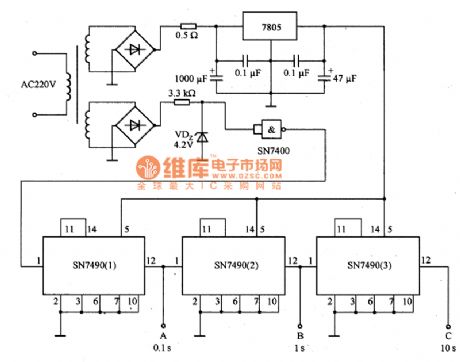
Picture 1 is delay pulse generating circuit of SN7490.They use 220V,50Hz AC as benchmark delay pulse generating circuit. In the circuit,A port can output 0.1s,B terminal outputs 1s and C end can output 10s time delay pulse.It can be used as benchmark pulse circuit and it is the basic form of digital counter the circuit.
Picture 1:Delay Pulse Generating Circuit of SN7490
(View)
View full Circuit Diagram | Comments | Reading(2068)
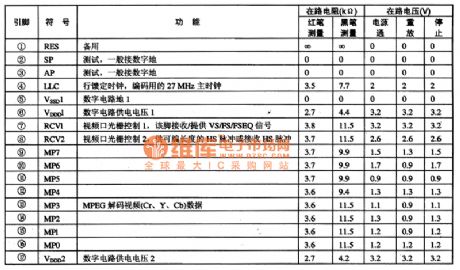
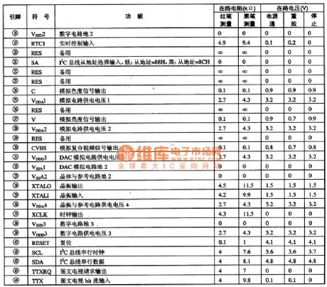
SAA7121 Digital Video Coding Integrated Circuit
Published:2011/8/25 22:47:00 Author:Michel | Keyword: Digital Video, Coding Integrated Circuit
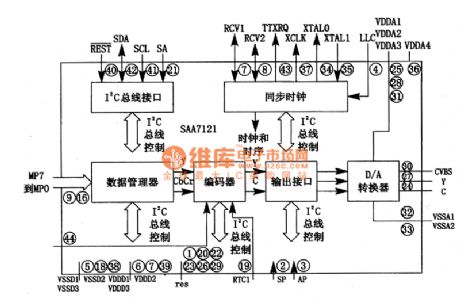
SAA7121 is digital video coding integrated circuit produced by Philips.It is widely used in VCD and DVD players.
First,Functions Features
SAA7121 integrated circuit supports NTSC and PAL-M B/G ~ TV pattern.It uses lzC control means and receives decompressed video data via the 8 bits of data bus.The built-in encoder codes digital brightness signal and chromaticity signal into the simulation CVSB and S video signal.It is composed of the data management unit, encoders, output interface, lObitD/A converter, synchronous clock circuit and the I2C bus interface and other components.Its inside circuit block diagram of intergrated block is shown as picture 1.
Picture 1:Inisde Circuit Block Diagram of SAA7121 Intergrated Block
Second,Pins Functions and Data
SAA7121 adopts 44 feet package and its pins functions and data are shown as picture 1. (View)
View full Circuit Diagram | Comments | Reading(1050)
Frequency Synthesizer Integrated Circuit of S14133T
Published:2011/8/25 22:46:00 Author:Michel | Keyword: Frequency Synthesizer, Integrated Circuit
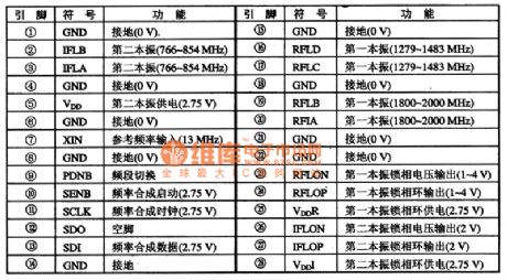
S14133T is frequency synthesizer integrated circuit and it is widely used in cellphones,such as TCL18 cellphones etc.
First,Functions Features S14133T integrated circuit contains first and second vibration,phase lock loop circuit, frequency synthesizer, clock and data circuit.
Second,Pins Functions and DataS14133T integrated circuit uses 28 feet and 4 columns flat type encapsulation,which is same as the S14133一MLP28 of Samsung A200 and A288 mobile phones but they could not exchange with each other.S14133T IC pins functions and data are shown as table 1.
Table 1:S14133T IC Pins Functions (View)
View full Circuit Diagram | Comments | Reading(947)
Battery Quick Charger Circuit of Digital Potentiometer XC9104
Published:2011/8/25 22:45:00 Author:Michel | Keyword: Digital Potentiometer, Battery Quick Charger Circuit

The above picture is battery quick charger circuit of digital potentiometer XC9104.When the power switch S1 switches on, 9 V voltage begins to charge the battery via LM317.When S1 switches on,Vw end voltage of XC9104 rises automatically,thus sliding port Vw is linked to VL end.In this state, A1 outputs high level, LM317 charges batteries quickly.The battery charges and the voltage gradually rises and XC9104 Vw end voltage rises automatically.A3 harmonic oscillator amplitude increases periodically according to the proportion that XC9104 remains. (View)
View full Circuit Diagram | Comments | Reading(2450)
PCA8516 Characters Form Integrated Circuit
Published:2011/8/25 22:43:00 Author:Michel | Keyword: Characters Form, Integrated Circuit

PCA8516 is character type integrated circuit that is produced by Philips Company and it is widely used in the big screen color TV,for example,ChangHong DT2O00 times frequency color TV.
PCA8516 integrated circuit contains the field line positioning pulse processing circuit, characters and clock oscillating circuit, characters and gezer signal circuit, character display vanishing circuit and some other auxiliary functions circuit. The IC adopts 24 DIP package and its pins functions and data are shown as table 1.
Table 1:PCA8516 Pins Functions and Data (View)
View full Circuit Diagram | Comments | Reading(603)
Impulse Current Prevention Circuit of Thyristor
Published:2011/8/25 22:41:00 Author:Michel | Keyword: Thyristor, Impulse Current, Prevention Circuit

This is impulse current prevention circuit of thyristor as above.When AC power supply is connected, the power switch may be burnt and smooth communication power supply circuit flows through larger impact current.In the circuit,thyristor VS1 makes the current prevent resistance from shortcircuit.The repeating/broken thyristor can work reliably and there is no necessary to worry about the contact's life problem. The delay time is determined by resistance R2 and capacitance C1.
If diodes VD3 ~ VD6 and smooth capacitance C2 are ignored ,impact current will be IP≤UP/R1=35.9A.Current limiting resistor R1 value is larger,the impulse current peak is smaller and but charging time of smooth capacitance grows longer. (View)
View full Circuit Diagram | Comments | Reading(737)
P85C28OAER System Control Microcomputer Integrated Circuit
Published:2011/8/25 22:44:00 Author:Michel | Keyword: System Control , Microcomputer, Integrated Circuit


P85C28OAER is system control microcomputer integrated circuit which is widely used in control chip of color displays the Philips and Lenovo etc.
First,Function Features
P85C28OAER integrated circuit contains the I2C bus of large scale integrated circuit microcomputer.It not only has all kinds of analog control circuits, keyboard switch decoding circuit and kinds of distortion.It also tests contorl without siganls,saving energy control,memeory work means and other various auxiliary functions.
Second,Pins Fuctions and DataP85C280AER adopts feet 42 DIP package and its pins functions and data is shown as table 1.
Table 1:Pins Functions and Data ofP85C28OAER IC (View)
View full Circuit Diagram | Comments | Reading(619)
0~2OV/1A Stable Precision Power Supply Circuit of LM199
Published:2011/9/8 1:20:00 Author:Michel | Keyword: Stable Precision , Power Supply Circuit

The picture is 0~2OV/1A stable precision power supply circuit of LM199.LM199is a drift integrated voltage modulewith a long-term stability and very small temperature . The circuit uses its output voltage source as the benchmark voltage power supply and that is 0 ~ 20 V adjustable stable power supply. RP1 uses 20 laps line potentiometer to change its resistance value,which can make the output voltage adjust between 0~20V.
VT1 transistor (LM395K) is used as the output circuit series control device.It is 5μA input base current and there are power transistor with overcurrent limiting and overheating protection functions.LM395K usually works in safety work range thus there is no necessary for external circuit to connect with overcurrent protection circuit,which makes the circuit very simple.In the circuit,RP1 needs to choose resistor with good temperature properties and R1 and R2need to choose metal film resistance with good temperature properties. (View)
View full Circuit Diagram | Comments | Reading(2037)
the agricultural liquid level automatic control circuit consisting of NE555
Published:2011/8/20 2:13:00 Author: | Keyword: the agricultural liquid level, automatic control

If just turns on the power ,the IC (555) ② pin is low level due to the voltage on C3 can't mutations when there isno water in the pool, 555 is set,high level outputby3-pinmakes the SSR end and the motor D is not running. At this point C3,C4 charge respectively through R1, R2, when the voltage on C4 charges to 2/3VDD, IC is reset,low level output by 3-pin makes SSR internal photoelectric coupler connect the AC voltage 220V, motor D has electricity and runs to pump water. When the water level rises to b probe, C4 is discharged through the water, but 555 still outputs low level,the motor D continues to run.
(View)
View full Circuit Diagram | Comments | Reading(3562)
High-speed complementary output voltage comparator circuit
Published:2011/8/20 2:10:00 Author: | Keyword: High-speed, complementary output, voltage comparator

LM161/261/361 transmission speed is high,it has the general power supply voltage and independent strobe terminal, it can output two complementary TTL signal that delays small and theinput disorder voltage is small,when driving over,the switching speed is small and it uses dual in-line type.The high-speed peak detector is shown as above.
(View)
View full Circuit Diagram | Comments | Reading(782)
The LED constant-current driver circuit based on LM2734
Published:2011/8/20 2:12:00 Author: | Keyword: constant-current driver
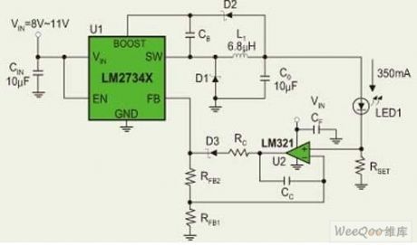
LM2734 is 1A buck regulator.Based on the LM2734 constant-current driver circuit (shown as above),the circuit uses LM321 operational amplifier to obtain the voltage of the sampling resistor Rset,then combines the other resistor and capacitor to form a complete,high-efficiency power LED constant current driver circuit.In actual use,some LED constant current driver circuit can get feedback voltage directly from the sampling resistor,it is shown as figure.
(View)
View full Circuit Diagram | Comments | Reading(2481)
The small power mini switch regulated power supply circuit formed by WS157 and WS106
Published:2011/9/3 2:53:00 Author:leo | Keyword: Small power, mini, switch regulated power supply

The picture shows a small power mini switch regulated power supply made by WS157 and WS106. WS157 and WS106 are a type of control component in regulated power supply. This kind of component integrates control circuit and power switch on the same chip which has the PWM controlling function and over current and over heat test function. It needs suitable switch transformer and some components to keep steady work situation. The regulate power supply made by it can directly convert the DV 220 V to low DC voltage. And the power of WS157 is 18 W while the power of WS106 is 12 W. (View)
View full Circuit Diagram | Comments | Reading(1726)
The drive LED typical application circuit
Published:2011/8/21 22:32:00 Author: | Keyword: drive LED, typical application
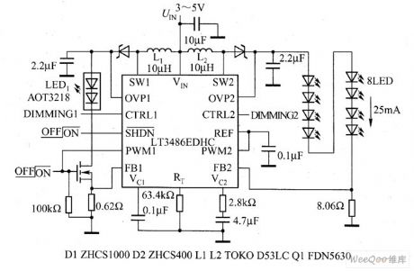
The dual-channel booster LT3486 produced by Linear Technology can drive 16 white light LEDs with a constant current(each channel has 8 serial LEDs), it can not only provide with PWM dimming, but also maintain the light color of the LED. It is fitted in portable electric equipment, car screens and other situations. LT3486 dims by controlling the working period of PWM, and the dimming range is 1000:1. It keeps the even LED brightness by the current mode and solid frequency.
(View)
View full Circuit Diagram | Comments | Reading(1000)
The main features of the amplifier pin signal--TL070/A JFET input op-amp
Published:2011/9/3 1:00:00 Author:Borg | Keyword: amplifier pin signal, JFET, input op-amp

TL070/A JFET input op-amp The input distortion voltage is 3mV; temperature drift is 10μV/℃; the biased current is 5pA; the gain band width is GB=3MHz; the rotating speed rate is 13V/μs; noise is 18nV/√Hz(1kHz); the differential mode input voltage is ±30V; the common input voltage is ±15V; the power consumption is 680mW.
(View)
View full Circuit Diagram | Comments | Reading(494)
The main features of the amplifier pin--the medium separation JFET op-amps of OPA404
Published:2011/8/23 22:35:00 Author:Borg | Keyword: amplifier pin, JFET op-amps

(View)
View full Circuit Diagram | Comments | Reading(654)
the winding circle number measuring instrument composed of 555
Published:2011/9/9 9:08:00 Author:Ariel Wang | Keyword: winding, circle number, measuring instrument

The measurement of the winding adopts the principle of magnetic pressure comparison .When the alternating current I goes to the winding which is to be measured and the standard winding Ws,the total magnetic motive force is:Vm=(Ws-Wx)i as two windings are series opposing .If Ws=Wx,then Vm=0.You can estimate the winding number to be measured by the standard winding number known.PSG is the multivibrator type oscillator composed of R1,R2,W1 and C1.The oscillation frequency is f=1.44/(R1+2R2+2Rw1)C1.The frequency range of parameter in the chart is 40~70Hz.You can adjust the oscillation frequency of potentiometer W1 to 50Hz. The drive stage is the class A push pull stage of power amplifier composed of BG2,BG3 and B1.
(View)
View full Circuit Diagram | Comments | Reading(594)
the machine which used to drive cats and dogs
Published:2011/9/9 9:12:00 Author:Ariel Wang | Keyword: cats, dogs, driver

The circuit of the machine which used to drive cats and dogs is seen as the chart.It emits high-power ultrasonic which is safe to human beings.In this way,themachine reaches its goal to threat and drive cats and dogs .And it can keep them away.
(View)
View full Circuit Diagram | Comments | Reading(652)
Circuit Diagram of 2576+358+Voltage Regulator Tube Pattern
Published:2011/9/9 9:08:00 Author:Zoey | Keyword: Voltage Regulator Tube
Advantages:
(1) As 2576 has an interior overcurrent and overtemperature-proof device, it can input constant voltage, constant current CC and overvoltage proof OVP together with 358, so as to achieve a reliable, safe and perfect charge solution of lithium cells.
(2) EMI design of automobile charger is relatively easy for 2576 is a fixed 52-k PWM convertor.
(3)Both 2576 and lm358 are made in high pressure and dual polar, so they are very firm.
(4)This solution is usually used in automobile charger of 0.8A~1.5A.
Disadvantages:
(1) Its system is complex and costly.
(2) CC and OVP control the 2576 EN by 358’s input, therefore, the charge current has a relatively large wave, and corresponding speed of CC and OVP is not prompt enough.
(View)
View full Circuit Diagram | Comments | Reading(1120)
| Pages:491/2234 At 20481482483484485486487488489490491492493494495496497498499500Under 20 |
Circuit Categories
power supply circuit
Amplifier Circuit
Basic Circuit
LED and Light Circuit
Sensor Circuit
Signal Processing
Electrical Equipment Circuit
Control Circuit
Remote Control Circuit
A/D-D/A Converter Circuit
Audio Circuit
Measuring and Test Circuit
Communication Circuit
Computer-Related Circuit
555 Circuit
Automotive Circuit
Repairing Circuit