
Circuit Diagram
Index 499
The regulator DC-DC circuit, power supply monitor pin and its main features AN7800R, etc
Published:2011/8/24 21:49:00 Author:Seven | Keyword: regulator DC-DC circuit, power supply, monitor pin

AN7800R and AN78M00R stabilizer (forward output with reset terminal) The output voltage solid stabilizer; the output voltages are 5V, 8V(AN78M08R only), 9V and 12V; AN7800R output current is 500mA; AN7800R output current is 1A; it has the reset terminal which controls output voltage conduction or breakdown; the maximum input voltage is 35V; power consumption is 10W; working temperature is -20~+80℃; it contains current control, over-heat protection, secure working area protection circuit. (View)
View full Circuit Diagram | Comments | Reading(677)
The regulator: DC-DC circuit, power supply monitor pin and its main features AN6541
Published:2011/8/24 21:48:00 Author:Seven | Keyword: DC-DC circuit, power supply, monitor pin, main features

AN6541 the 3-terminal regulator This is a 3-terminal regulator whose output voltage is fixed; the output votlage is 9V; output current is 300mA; the typical voltage difference value between minimum output and input is 0.3V; the output voltage temperature coefficient is ±0.01%℃; maximum input voltage is 20V; power consumption is 15W; working temperature is -30~+80℃; it contains output current limiting protection circuit.
(View)
View full Circuit Diagram | Comments | Reading(568)
CF1456 Double-Power General-Type Single-Supply Amplifier Circuit Diagram
Published:2011/9/7 0:47:00 Author:Vicky | Keyword: Double-Power General-Type Single-Supply
CF1456 series operational amplifier is a inner-complementing type high-gaining amplifier. Its input current is relatively low, and power dissipation is very low. There is zero-setting end exteriorly, which has short-circuit protection and over-voltage protection functions. It is available in summing amplifier and intefrator. The analog types or substitutions are CFl556MT、CF1456CT、CF1556MD、CF1456CD、CF1556MJ、CF1456CJ、CF1456CP etc. (View)
View full Circuit Diagram | Comments | Reading(549)
The regulator: DC-DC circuit, power supply monitor pin and its main features AN6540
Published:2011/8/24 21:47:00 Author:Seven | Keyword: DC-DC circuit, power supply, monitor pin

AN6540 the step-up time adjustable regulator (forward input) This is a 4-terminal stabilizer whose output voltage is stable and step-up time is adjustable; the output voltage is 8.5V; the minimum input and output voltage difference typical value is 0.3V; the maximum voltage is 20V; the working temperature is -30~+80℃; it contains output current limiting protection circuit.
(View)
View full Circuit Diagram | Comments | Reading(733)
The regulator: DC-DC circuit, power supply monitor pin and its main features AN5905
Published:2011/8/24 21:47:00 Author:Seven | Keyword: DC-DC circuit, power supply, monitor pin

This is a switch stabilizer control circuit; its oscillating frequency can be doubled or quadrupled; it contains the soft starting circuit; the max power supply voltage is 14.4V; power consumption is 230mW; the working temperature is -20~+70℃; it contains the over-current protection circuit.
(View)
View full Circuit Diagram | Comments | Reading(568)
The regulator: DC-DC circuit, power supply monitor pin and its main features AN900
Published:2011/8/24 21:47:00 Author:Seven | Keyword: DC-DC circuit, power supply, monitor pin

AN900--the switch stabilizer control circuit This is a switch stabilizer control circuit which contains a soft starting circuit; the duty cycle is 0~0.7; it can be triggered externally; the Vref depends on the external Zener diode; the max power supply voltage is 14.4V; the max power supply current is 18mA; the working temperature is -20~+75℃; it contains the over-voltage, over-current, high power supply voltage, low power supply voltage and other protection circuit.
(View)
View full Circuit Diagram | Comments | Reading(657)
The regulator: DC-DC circuit, power supply monitor pin and its main features AD581
Published:2011/8/24 21:46:00 Author:Seven | Keyword: DC-DC circuit, power supply, monitor pin

AD581 reference voltage circuit (+10V) This is a wide-band 3-terminal Vref circuit; its output voltage is 2.5V; the output voltage is 10V; the primary fault of AD581L/581U output voltage is ±5mV; When it is 0~70℃, the temperature drift of AD581L is 5*10-6/℃, when it is -55~+125℃, the temperature drift of AD581U is 10*10-6/℃; the long-term stability is 25*10-6/1000h; the input voltage range is 12~40V; the output current is 10mA; the -10V Vref power supply can be the 2-terminal Zener diode; when the environment temperature is lower than 25℃, the power consumption is 600mW.
(View)
View full Circuit Diagram | Comments | Reading(557)
Typical application circuit of intelligent temperature controller MAX6641 based on SMbus
Published:2011/9/8 8:09:00 Author:Felicity | Keyword: intelligent temperature controller

Typical application circuit of MAX6641 is shown in the figure. Using the PWMOUT terminal to drive N-MOSFET and to control the rotational speed of the pan. Remote PN junction temperature sensor can be replaced by the emitter of the triode inside micro processor (μP). Discrete component triode as CMPT3906、T3906、KST3906-TF、SMBT3906 etc. can also be adopted. Under the highest expected temperature and 10μA current the forward voltage drop of the emitter shall above 0.25V ; Under the lowest expected temperature and 100μA current the forward voltage drop of the emitter shall above 0.95V. High power triode shall not be adopted.
(View)
View full Circuit Diagram | Comments | Reading(945)
The regulator: DC-DC circuit, power supply monitor pin and its main features 7800
Published:2011/8/24 21:44:00 Author:Seven | Keyword: DC-DC circuit, power supply, monitor pin

7800 serial 3-terminal stabilizer (forward output) This is a 3-terminal stabilizer whose output voltage is stable; the output voltages are 5V, 6V, 7V, 8V,9V,10V,V12V,15V, 18V, 20V and 24V; output current is 1A; the output voltage range is 5~18V; the maximum output voltages are 35V, 20V 24V and 40V respectively; the working temperature of 7800 is -55~150℃, and the 7800C working temperature is 0~+125℃; it contains the over-current limitation and secure working area protection circuit. The approaching modes are μA7800, LM7800, MC7800, HA7800P, μPC7800M, NJM7800, TA7800AP, AN7800 and CW7800.
(View)
View full Circuit Diagram | Comments | Reading(558)
Single-chip RF Power Measurement System MAX2015-made RF Signal Reception Srength Idicator Crcuit
Published:2011/5/16 4:37:00 Author:Sharon | Keyword: Single-chip, RF Power Measurement, Signal Reception Srength Idicator

RF signal receiving strength indicator circuit formed by MAX2015 is as shown in the figure. RF signals pass through the coupling capacitor C1 to IN +end and IN-end,then to ground by the coupling capacitor C2. IN +, IN-end internal 50Ω resistor can be matched with the 50MHz ~ 3.0GHz RF circuits. The capacity of C1 and C2 are both 680pF. C3 and C4 are power supply decoupling capacitors. Link OUT and SET-side to each other by short circuit, and MAX2015 will enter the test mode. The output voltage Uo of OUT terminal is sent to the digital voltage meter, showing the received RF signal strength.
When power supply is Ucc=+2.7~3.6V, R=0Ω; when Ucc=+4.75~5.25V, R=75Ω( Difference ranging between -1% and +1% is allowable).PWDN is should be linked to ground. (View)
View full Circuit Diagram | Comments | Reading(1222)
Photoelectric Encoder Phase Counting Circuit
Published:2011/5/17 3:03:00 Author:Sharon | Keyword: Photoelectric Encoder, Phase Counting
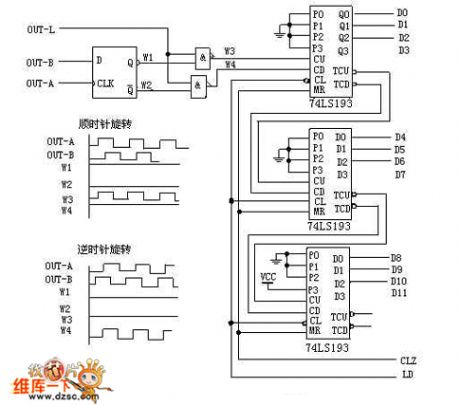
When the photoelectric encoder rotates clockwise, the channel A is ahead of Channel B 90°by output waveform. D flip-flop output Q (waveform W1) is high, and Q (waveform W2) is low.The top nonconjunction gate is open, and the counting pulses pass through (waveform W3), and then are sent to bi-directional counter 74LS193's plus pulse inputs CU for the addition count; At this point, the bottom nonconjunction gate is closed, the output is high(waveform W4). When the photoelectric encoder rotates counter-clockwise, channel A legs behind Channel B 90°in output waveform. D flip-flop output Q (waveform W1) is low, and Q (waveform W2) is high. The top nonconjunction gate is closed, and the output is high (waveform W3); At this point, the bottom nonconjunction gate is open, counting pulses get through (waveform W4), and are sent to decrease pulse input CD of the two-way counter 74LS193 CD for the subtraction count. (View)
View full Circuit Diagram | Comments | Reading(2914)
The magnetic eraser energy-saving controller
Published:2011/8/23 22:36:00 Author:qqtang | Keyword: magnetic eraser, energy-saving controller

The working principle of the circuit
The magnetic eraser energy-saving controller circuit consists of the relay K, transistor V, time-based integrated circuit IC, diode VD, resistors of R1 and R2, potentiometer RP, capacitors of C1 and C2, battery GB, stroke switch and hand/auto control switch S1 and so on, see as figure 8-147.
All the knife-switch Q, starting key S3, stop key S2 and AC contactor KM are the former hand control line of the magnetic eraser.
When it is under auto control, the control switch S1 is reset (auto), at the moment, the normally closed contactor is getting through, the normally open contactor is turned off, the control circuit isn't working because of the breaking down of the negative pole.
(View)
View full Circuit Diagram | Comments | Reading(1342)
Overheating Protection Circuit (using PTC thermistor)
Published:2011/5/17 21:17:00 Author:Sharon | Keyword: Overheating Protection, PTC thermistor


For continuously operating mechanical and electrical equipment used in production like automatic lathes, electric oven, and ball mill and other and other unattended devices, due to the motor overheating or accident caused by thermostat failures have occurred not rare, it's necessary to take appropriate security measures. PTC thermistor overheating protection circuit can be easily and effectively to prevent such incidents from occurring.
1. Principle circuitFigure 1 is an example of motor overheat protection. It's a control circuit composed bythe PTC thermistor and the Schmitt circuits. In the figure, RT1, RT2 and RT3 are three step-type PTC thermistors of the same characteristics. They were buried in the stator windings. Under normal circumstances, PTC thermistor is in room temperature, and their total resistance is less than 1KΩ. At this point, V1 pauses, V2 turns on, and the relay K is through and open normally. The motor is powered by city electricity.
Figure 1 Motor overheating protection control circuit
2. The main components election The choice of PTC thermistor depends on the motor insulation class. Components dimensions are shown in Figure 2. Usually, the choice of Curie temperature of PTC thermistor is 40℃ lower than the limit temperature which corresponds to the motor insulation level.
Figure 2 PTC thermistor Dimensions
3 Installation and adjustmentThe recommended installation way is to bury PTC thermistor in the stator windings. Adjustment method: Put PTC thermistor in incubators, set the temperature TK, regulate RP to make that when PTC thermistor stays at TK-5 ℃, VD2 does not shine, K does not move; while when it stays at TK +5 ℃, VD2 lights, K acts. RP can be locked.
(View)
View full Circuit Diagram | Comments | Reading(2975)
The linear matrix CCD driver designed on the base of FPGA
Published:2011/8/31 18:57:00 Author:qqtang | Keyword: linear matrix, CCD driver, FPGA
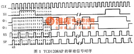
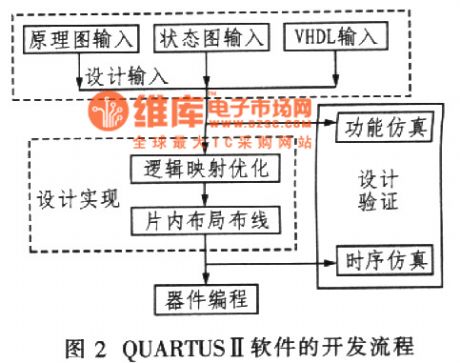
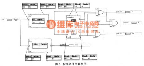
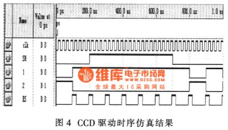
CCD(Charge Coupled Devices) characterizes small size, high precision, low power consumption, long lifespan and auto electric scanning,etx, which is widely used in image sensing and non-touching measurement arear. As the the photoelectric features, such as the switching efficiency and SNR, reach the best values only when it is under the proper sequence, then it is outputting stable and reliable signals, therefore, the design of the circuit drive is one of its key problems in application.
(View)
View full Circuit Diagram | Comments | Reading(2121)
The constant temperature control circuit composed of 3-line serial spot intelligent temperature sensor DS1620
Published:2011/9/5 22:58:00 Author:qqtang | Keyword: constant temperature control circuit, serial spot, intelligent temperature sensor
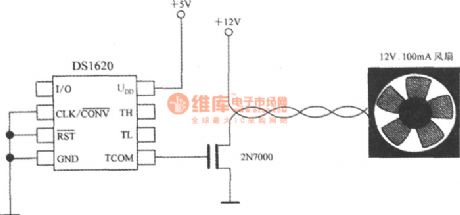
When DS1620 is used to supervise the microprocessor temperature, by opening or closing the fan, the radiation condition can be changed, so the temperature control can be done, see as the figure. Its feature is that TCOM signal controls the fan by 2N7000 MOSFET, when the temperature of the chip surface is higher than tH, the fan is turning on, and the state will last till t
(View)
View full Circuit Diagram | Comments | Reading(1701)
Seashore biofeedback therapy device circuit diagram
Published:2011/9/8 21:00:00 Author:Lucas | Keyword: Seashore biofeedback, therapy device
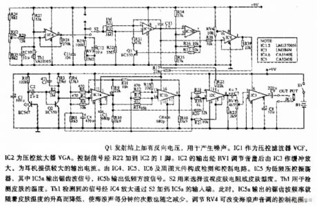
The Q1 emitter junction is added reverse voltage for generating noise. IC1 is used as a voltage-controlled filter VCF, and IC2 is the voltage-controlled amplifier VGA. Controlling signal is added to the pin 1 of IC2 by R22. IC1's output is adjusted by RV1, then buffered and amplified by IC3 to provide a larger output current for the headphones. The IC4, IC5, IC6 and the surrounding components form the detection and control circuit. IC5 is the low-frequency voltage-controlled oscillator, and IC5a outputs sawtooth signal, IC5b outputs low-frequency square wave signal. S2 is used to select monitoring skin resistance or skin temperature.
(View)
View full Circuit Diagram | Comments | Reading(2432)
Electric Blanket Temperature Control Circuit
Published:2011/5/17 4:35:00 Author:Sharon | Keyword: Electric Blanket, Temperature Control

Electric blanket without temperature controller not only can hardly obtain a comfortable bed temperature, but also has huge energy consumption. What's worse, there may be fire hazard. Electric blanket with bimetallic thermostat although has improvements in energy-saving and security, but it's still difficult for it to adjust the temperature. Temperature control circuit with a PTC thermistor can overcome these shortcomings.
1. Principle circuit The electric blanket temperature control circuit is consistuted by the rectifier circuit and the temperature measurement and control circuit. Its principle is shown in Figure 2.11.1. Chart, RT1 and RT2 are the PTC thermistor for detecting the temperature of different regions, and also form a SCR VS trigger circuit together with the RP, C and VD6. RP also has the function of defaulting the constant temperature values.
2. Main components selectionPTC thermistor should be selected with Curie temperature 30 ℃, temperature resistance 5KΩ, and withstanding voltage 500V or more. VS should be chosen by the size of RL power. The circuit model selected here can meet the general use of electric blankets. C selects the best insulation performance polycarbonate film capacitors.
3. Installation and adjustmentThe recommended installation method is burying two PTC thermistors in the intensive sites of the electric wires. For example, the center of the feet and waist. In addition, the circuit is connected directly with the city electricity, and the PTC thermistor buried in the electric blanket and its terminations should have good insulation measures.
(View)
View full Circuit Diagram | Comments | Reading(4721)
Triangle multidrop parallel connection three-phase motor winding short circuit detection circuit
Published:2011/9/8 20:01:00 Author:Christina | Keyword: Triangle, multidrop, parallel connection, three-phase, motor, winding, short circuit, detection circuit

For the triangle multidrop parallel connection three-phase motor, you need to separates the adapter connector of the winding. As the figure shows, you can connect the winding into the triangle, and connect one port with the secondary stage of the welding transformer T, another port of T is connected with an ammeter. After the power is connected, you need to connect the hand (which is connected with the ammeter) with the other two ends of the winding respectively to compare the current, the phase which has the smaller current value is the short circuit winding.
(View)
View full Circuit Diagram | Comments | Reading(3137)
Disinfection cabinet electronic control circuit
Published:2011/9/8 20:01:00 Author:Christina | Keyword: Disinfection cabinet, electronic control circuit

The control circuit is composed of the AC step-down regulator circuit, the infrared heating circuit and the timing control circuit. The single phase alternating current adds to the primary stage of the transformer T through the temperature limit fuse FU, and it is reduced, rectified and stabilized by the circuit to change into the 9V DC voltage, this DC voltage adds to the positive pole of the one-way SCR through the normally closed contact point K1(1-3).
The AN1 is the power control button, you can conduct the SCR and control the connection of the power supply by pressing this button. AN3 is the infrared heating start button, if you press this button, the low level of the 555's pin-2 will make the 555 in the trigger & set state. The monostable timing circuit is composed of the 555 and R5, R6, C4, C5.
(View)
View full Circuit Diagram | Comments | Reading(814)
Microwave detection radio alarm 26P27
Published:2011/9/8 19:55:00 Author:TaoXi | Keyword: Microwave, detection, radio alarm

In figure (a), when the detection circuit TWH9250 detects the target signal, the output port 0 of it outputs the low level, the relay K is connected. When the transmitter circuit gets the operating power supply, the address code which is edited by the coding circuit YYH26 is amplified by the ampP27A, and it is output by the antenna. The detection circuit can be used to connect the operating power supply of the transmitter, the transmitter circuit outputs the address code to indicate the detection place. Figure (b) shows the multi-channel receiver alarm circuit.
(View)
View full Circuit Diagram | Comments | Reading(936)
| Pages:499/2234 At 20481482483484485486487488489490491492493494495496497498499500Under 20 |
Circuit Categories
power supply circuit
Amplifier Circuit
Basic Circuit
LED and Light Circuit
Sensor Circuit
Signal Processing
Electrical Equipment Circuit
Control Circuit
Remote Control Circuit
A/D-D/A Converter Circuit
Audio Circuit
Measuring and Test Circuit
Communication Circuit
Computer-Related Circuit
555 Circuit
Automotive Circuit
Repairing Circuit