Sensor Circuit
Photoelectric Encoder Phase Counting Circuit
Published:2011/5/17 3:03:00 Author:Sharon | Keyword: Photoelectric Encoder, Phase Counting | From:SeekIC

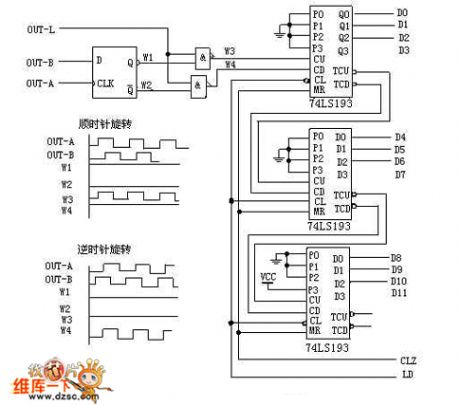
When the photoelectric encoder rotates clockwise, the channel A is ahead of Channel B 90°by output waveform. D flip-flop output Q (waveform W1) is high, and Q (waveform W2) is low.The top nonconjunction gate is open, and the counting pulses pass through (waveform W3), and then are sent to bi-directional counter 74LS193's plus pulse inputs CU for the addition count; At this point, the bottom nonconjunction gate is closed, the output is high(waveform W4). When the photoelectric encoder rotates counter-clockwise, channel A legs behind Channel B 90°in output waveform. D flip-flop output Q (waveform W1) is low, and Q (waveform W2) is high. The top nonconjunction gate is closed, and the output is high (waveform W3); At this point, the bottom nonconjunction gate is open, counting pulses get through (waveform W4), and are sent to decrease pulse input CD of the two-way counter 74LS193 CD for the subtraction count.
Reprinted Url Of This Article:
http://www.seekic.com/circuit_diagram/Sensor_Circuit/Photoelectric_Encoder_Phase_Counting_Circuit.html
Print this Page | Comments | Reading(3)

Article Categories
power supply circuit
Amplifier Circuit
Basic Circuit
LED and Light Circuit
Sensor Circuit
Signal Processing
Electrical Equipment Circuit
Control Circuit
Remote Control Circuit
A/D-D/A Converter Circuit
Audio Circuit
Measuring and Test Circuit
Communication Circuit
Computer-Related Circuit
555 Circuit
Automotive Circuit
Repairing Circuit
Code: