Medical
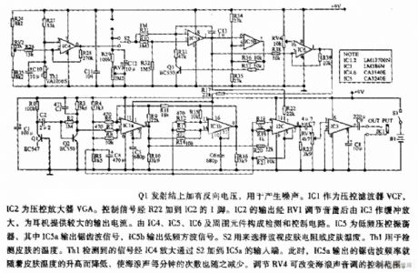
Seashore biofeedback therapy device circuit diagram
Published:2011/9/8 21:00:00 Author:Lucas | Keyword: Seashore biofeedback, therapy device | From:SeekIC

The Q1 emitter junction is added reverse voltage for generating noise. IC1 is used as a voltage-controlled filter VCF, and IC2 is the voltage-controlled amplifier VGA. Controlling signal is added to the pin 1 of IC2 by R22. IC1's output is adjusted by RV1, then buffered and amplified by IC3 to provide a larger output current for the headphones. The IC4, IC5, IC6 and the surrounding components form the detection and control circuit. IC5 is the low-frequency voltage-controlled oscillator, and IC5a outputs sawtooth signal, IC5b outputs low-frequency square wave signal. S2 is used to select monitoring skin resistance or skin temperature.
Reprinted Url Of This Article:
http://www.seekic.com/circuit_diagram/Electrical_Equipment_Circuit/Medical/Seashore_biofeedback_therapy_device_circuit_diagram.html
Print this Page | Comments | Reading(3)

Article Categories
power supply circuit
Amplifier Circuit
Basic Circuit
LED and Light Circuit
Sensor Circuit
Signal Processing
Electrical Equipment Circuit
Control Circuit
Remote Control Circuit
A/D-D/A Converter Circuit
Audio Circuit
Measuring and Test Circuit
Communication Circuit
Computer-Related Circuit
555 Circuit
Automotive Circuit
Repairing Circuit
Code: