
Circuit Diagram
Index 496
TC1948P video tape recorder infrared remote control launch circuit
Published:2011/9/4 20:31:00 Author:TaoXi | Keyword: video tape recorder, infrared, remote control, launch circuit
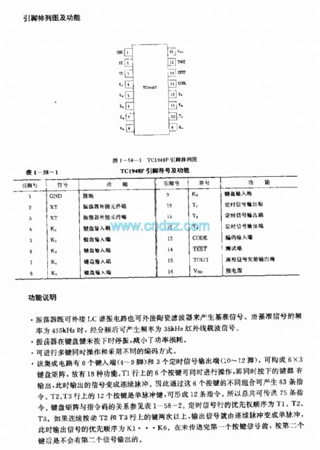


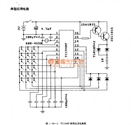
The TC1948P is designed as one kind of infrared remote control launch circuit that can be used in the video tape recorder application. The internal circuit is composed of the keyboard input circuit, the oscillator, the timing signal generator, the code signal generator, the decoder, the synchronous/single pulse signal generator and the output signal. The difference between the M50115P, M50115AP, M50115BP and M50115CP is the identification number.
Features
CMOS technology, the power consumption is low.The power supply voltage operating range is wide, and it can work in low voltage.16-pin dual-row DIP plastic package.
Function description
This oscillator can be connected with the LC resonant circuit and the ceramic filter to produce the reference signal.The oscillator will stop working when the button is not pressed to reduce the power consumption.
(View)
View full Circuit Diagram | Comments | Reading(1796)
TC9132P remote control transmission line circuit
Published:2011/9/8 19:53:00 Author:TaoXi | Keyword: remote control, transmission line
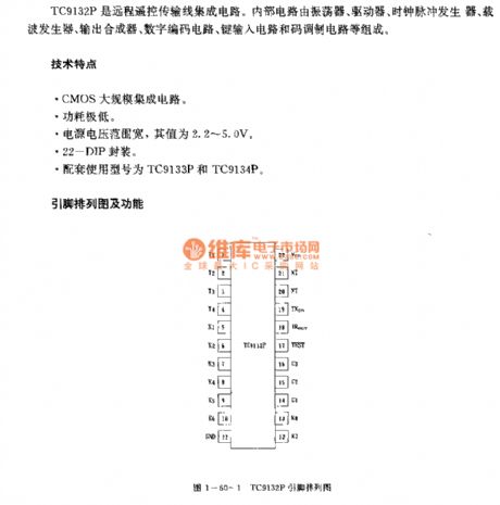

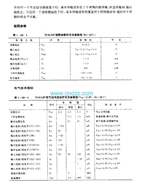
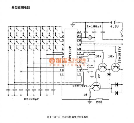
The TC9132P is designed as one kind of remote control transmission line circuit. The internal circuit is composed of the oscillator, the driver, the clock pulse generator, the carrier frequency generator, the output synthesizer, digital coding circuit, key input circuit and the code modulation circuit.
Features
CMOS large scale integrated circuit.The power consumption is low.The power supply voltage range is wide, the value is 2.2-5.0V.The 22-DIP package.The matching models are TC9133P and TC9134P.
Function description
It forms the remote control system which has 32 kinds of functions with the TC9133P or TC9134P.It forms the oscillator with the LC circuit or the ceramic resonator. The carrier frequency depends on the oscillation frequency.It supplies the display output.
(View)
View full Circuit Diagram | Comments | Reading(1488)
TC9012F TV, VCR and CD player infrared remote control launch circuit
Published:2011/9/4 20:32:00 Author:TaoXi | Keyword: TV, VCR, CD player, infrared, remote control, launch circuit
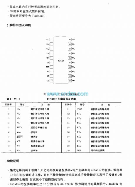
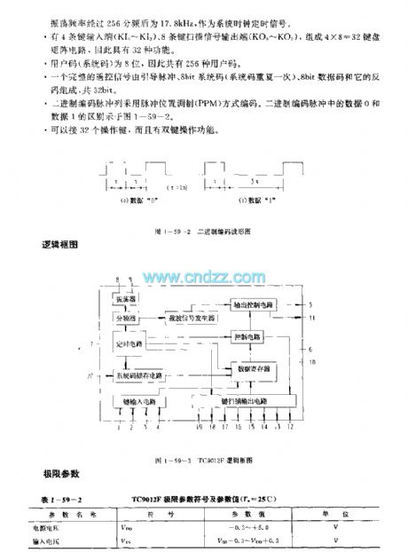
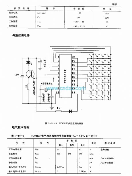
The TC9012F is designed as one kind of infrared remote control launch circuit that can be used in the TV, VCR and CD player applications. The internal circuit is composed of the oscillator, the frequency divider, the timing circuit, the system code latch circuit, the key input circuit, the key scanning output circuit, the output control circuit, the carrier signal generator, the control circuit and the data register.
Features
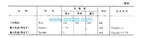
It uses the CMOS technology.The power voltage is low, the value is 2-4V.The power consumption is low. The current is lower than 20mA when this deivce is operating; and in the holding state, the current is lower than 1uA.Higher emission efficiency, the duty ratio of the LED is 1.8%.It has the emission display output port.The IC has the oscillation circuit with the clock oscillator.20-pin dual-row DIP plastic package.The matching model is TA8141S.
(View)
View full Circuit Diagram | Comments | Reading(1534)
YN5049/YN5050 TV, VCR and stereo equipment infrared remote control launch circuit
Published:2011/9/4 20:33:00 Author:TaoXi | Keyword: TV, VCR, stereo equipment, infrared, remote control, launch circuit


Features
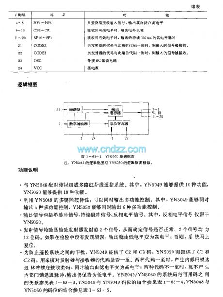
The oscillator has only one input port.The code detection circuit can prevent the interference of other circuits.It has strong noise eliminating ability.The matching model is YN5048.
Function description
It can be used with the YN5048 to form the multi-channel infrared remote control system. The YN5049 can supply 10 kinds of functions, the YN5049 can supply 18 kinds of functions.It can output the multi-function control by using the multikey pressing-together feature. The YN5049 can output 5 kinds of multi-function controls, the YN5050 can output 6 kinds of multi-function controls.The output signal includes the single pulse signal, the continuous pulse signal, the inverse level signal.
(View)
View full Circuit Diagram | Comments | Reading(1197)
Two On-off Circuits controlled by CMOS System Direct Motor
Published:2011/9/3 10:22:00 Author:Zoey | Keyword: On-off Circuits, CMOS System, Direct Current, Motor

Circuit (a) is controlled by 24-V and 18-A direct current motor CMOS. NPN reset tube 2N282 needs to get 20A current, and Q1 150mA. Circuit (b) is controlled by CMOS direct current motor that can input high level, the Darlington uses a PNP 2N6285,collector power of the incentive transistor Q1 is not connected to CMOS power, instead, it should be connected to the TV power. (View)
View full Circuit Diagram | Comments | Reading(1189)
Space-saving HVArc Guard Capacitor goes for Passive Buffering Circuit
Published:2011/9/3 10:25:00 Author:Zoey | Keyword: Space-saving, HVArc Guard Capacitor, Passive Buffering
Many passive accessories can be used to make passive buffering circuits, and to absorb energy of reactance on switched circuits. Buffering circuits can pinchoff pulse noise, reduce power losses while cutting off circuits and reduce peak voltage on switches.
New HVArc Guard high pressure MLCC capacitor gathers the attributes such as high breakdown, low impedance, and wide work frequency scale together. What’s more, its size is as small as 0805.
HVArc Guard have excellent surge restrain capability. Here are the statistics for surge test on HVArc Guard capacitor.
C0G(N0P)HVArc Guard X7R HVArc Guard
1.2μs×50μs 1650V 500V
10μs×700μs 1800V 1200V
10μs×160μs >1500V 1200V
Following picture is an example for buffering circuit of totem pole MOSFET circuit. (View)
View full Circuit Diagram | Comments | Reading(596)
Diamond-shaped Bridge Analog Switched Circuit
Published:2011/9/3 10:27:00 Author:Zoey | Keyword: Diamond-shaped, Bridge, Analog Switched Circuit
Following picture refers to the diamond-shaped bridge analog switched circuit, this circuit can turn on and turn off analog signals that have a peak of 3v in 3ns. Symmetrical drive circuits can switch on and switch off quadruple transistor diamond-shaped bridge circuits with a clock frequency of 20MHz. Typical ascending time of 1-v direct current analog input signal is 1.5ns, descending time is 2ns. This circuit can meet the sampling-maintenance requirements of multiplex converter and pulse code modern remote-testing modulator that has a frequency of 100Mb/s. (View)
View full Circuit Diagram | Comments | Reading(867)
Logic-control Analog Switched Circuit
Published:2011/9/3 10:30:00 Author:Zoey | Keyword: Logic-control, Analog Switched Circuit
The logic-control analog switched circuit has been shown in the following picture. This switched circuit adopts 2N4860 junction field effect transistor, so its conduction resistance is only 20Ωand the pinchoff drain current is small. Operational amplifier LM102 constitutes a voltage follower and plays an important role in buffering. S67800 voltage converter can drive the switched circuit if controlled by DTL and TIL level. (View)
View full Circuit Diagram | Comments | Reading(795)
Servo Circuit
Published:2011/9/3 10:31:00 Author:Zoey | Keyword: Servo Circuit
Following picture shows the servo circuit, this switched circuit uses μA795 Analog multiplier and μA741 operational amplifier to produce AC error signals, and then drives the two-phase servo electronic machine, the direct input signal will be added to pin9,and AC signal will be added to pin 4 via R1 and C1, servo position signal will be added to pin 12. The multiplier takes the signal margin of pin 9 and pin 12 and multiply it by signals on pin 4, then input the value to operational amplifier from pin 14. As soon as actions of the servo electronic machine equalize voltage on pin 9 and pin 12, the system will turn to be 0. (View)
View full Circuit Diagram | Comments | Reading(711)
A Time Circuit Diagram for Improving Anti-jamming Performance
Published:2011/9/3 10:33:00 Author:Zoey | Keyword: Time Circuit Diagram, Anti-jamming Performance
A Time circuit diagram for improving anti-jamming performance has been shown in following picture. In practical, high-frequency spark jamming, electromagnetism jamming as well as the absorption and release of relays often do harm to the circuit. This circuit has strong anti-jamming performance. BG3 and 2DW7 constitute a step-down voltage circuit, interfere the filter of 24V power supply. After increasing the magnitude of trigger pulse, BG1 and DW2 will constitute a high threshold inverting amplifier, small-magnitude jamming pulse will be prevented.BG2 and other resistances and capacitors are used to filter narrow pulse jamming. (View)
View full Circuit Diagram | Comments | Reading(712)
A One-hour Timer Circuit
Published:2011/9/3 10:34:00 Author:Zoey | Keyword: One-hour, Timer Circuit
The one-hour timer circuit has been shown in following picture. This circuit adopts high input resistance FET to input operational amplifier 3140, so as to add timing scale of 555 timer to its 100 times. Choose proportion of R3/R2 to change the multiplier index. Delay time is T=[(R2+R3)/R2] (1386R1C1), parameter in the picture is T=100R1C1= 1 hour. (View)
View full Circuit Diagram | Comments | Reading(1255)
A Stable Timer Circuit Diagram of Four-Transistor
Published:2011/9/3 19:56:00 Author:Zoey | Keyword: Stable Timer Circuit , Four-Transistor
(View)
View full Circuit Diagram | Comments | Reading(1038)
A Passive Light-controlled Switched Circuit Diagram
Published:2011/9/3 19:59:00 Author:Zoey | Keyword: Passive, Light-controlled, Switched Circuit Diagram
Following picture shows the passive light-controlled switched circuit. Generally, light-controlled switches need power supply. Although integrated light-controlled controllable silicon switches do not need power supply, they have to satisfy the requirements such as high sensitivity and high pressure resistance. Circuit (a) is a passive light-controlled direct current switch, therein, 2CR1 and 2CR2 are closed gate high-speed light cell, they are used to receive light signals, produce voltage and input current. Circuit (b) is a passive light-controlled AC switch, if the load current is not large enough, it can set the load on AC trigger directly and it can work without the AC trigger.
(View)
View full Circuit Diagram | Comments | Reading(640)
555 Water level-controlled Circuit
Published:2011/9/3 10:40:00 Author:Zoey | Keyword: Water level-controlled
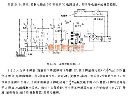
As shown in the picture 24-24, the controlling circuit is composed of 555 and a music IC circuit. This circuit is used to control the conductive liquid.
1,2,3, and 4 refer to four pins. When the liquid level goes down and Pin 3 is exposed, Pin 2 of IC1will bein low level(<1/3VDD), 555 will set and J will close, and solenoid valve will get electrical power and begin to work and infuse water to the container. Meanwhile, IC2 will be triggered and play music to inform people to infuse water. When water levelreachespin 2, water resistance between pin 1 and pin 2 will make the level of pin 6 higher than 2/3VDD, then 555 will reset, pin 3 will be in low level, J willrelease, and solenoid valve will cut off electric power and water supply. Pin 4 is an insurance needle, when water level reaches pin 4, VT1 will conduct and be in low level, forcing 555 to reset and cut off the solenoid valve. (View)
View full Circuit Diagram | Comments | Reading(1324)
Circuit of a 555 Multi-vibrator with a changeable tone
Published:2011/9/3 10:38:00 Author:Zoey | Keyword: 555 Multi-vibrator, a changeable tone
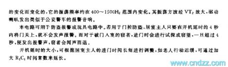
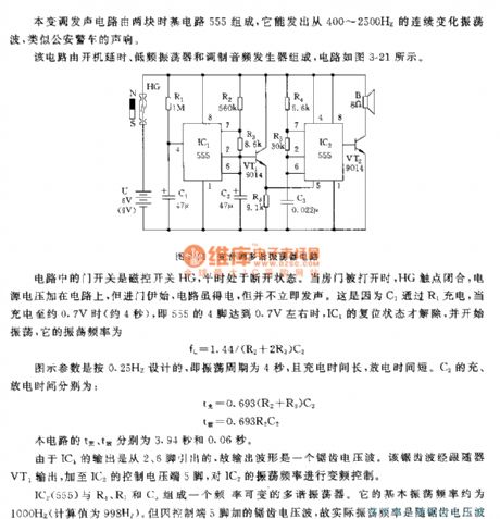
This transposition circuit is composed of two time-based 555 circuit, it can emit continuous oscillation wave that ranges from 400~2500 Hz, similar to the sound of police wagon.
This circuit consists of time-lapse oscillator, low-frequency oscillator and modem audio generator; the circuit can be seen in the picture3-21.
The gating switch HG is magnet-controlled and it remains open usually. When IC1 ceases to be reposited and starts to oscillate, the oscillation frequency is
fc=1.44/(R2+2R3)C2
The charge and discharge time of C2 is 3.94s and 0.06s respectively. Output wave of C2 is sawtooth voltage wave, which controls the oscillation frequency conversely.
The multi-vibrator is composed of IC2,R4, R5 and C3, with its frequency can be changed. Its basic oscillation frequency is about 1000Hz, and its actual oscillation frequency changes as sawtooth voltage wave change. The oscillation square wave will be magnified through VT2, and then drive the speaker to make an alarm that sounds like the police wagon.
The circuit can be used in burglarproof system and circuit of various toys, the prolonged time of start-up can be adjusted according to the time takes for housemasters to enter the house. For example, it takes longer time for old people to enter the house, so we can prolong the time by enlarging the time constant of R1C1. (View)
View full Circuit Diagram | Comments | Reading(1444)
Sine wave output circuit composed of the TL082
Published:2011/8/24 21:30:00 Author:Christina | Keyword: Sine wave, output circuit
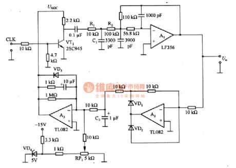
The sine wave output circuit which is composed of the TL082. The CLK is the input clock signal, it has the frequency division effect to the signal which is produced by the crystal oscillator and it changes the signal into the 1 kHZ clock signal. VT1 is the amplitude modulation circuit, we use the 1 kHZ clock signal to control the on/off of the control voltage UAGC to make it produce the square wave, and then we use the low-pass filter to filter out the higher harmonic. The R1 and C1 can be used to set the time constant of the rising edge of the square wave, the c=3~A (c is the cutoff frequency of the wave filter). in order to design the filter accurately, we can set the buffer amplifier A1 to isolate the R1 and R2.
(View)
View full Circuit Diagram | Comments | Reading(2112)
Ladder wave generation circuit composed of the 74HC193
Published:2011/8/24 21:30:00 Author:Christina | Keyword: Ladder wave, generation circuit

The ladder wave generation circuit which is composed of the 74HC193 is as shown in the figure. In this circuit, the 74HC193 is the 4-bit binary counter, we can connect the R-2R trapezoidal resistance network at the output port of it to form the 4-bit D/A converter. The number 15 stage voltage is the value of the trapezoidal network, 5Vxl5/16=4.6875V, the voltage of every stage is 312.5mV. In order to make the maximum output voltage is 10V, we use the A1 to amplify it 2 times. When the stepped voltage of every stage is not suitable, we can divide it at the output port.
(View)
View full Circuit Diagram | Comments | Reading(3311)
Humidity measurement circuit with the thermistor
Published:2011/8/24 21:30:00 Author:Christina | Keyword: Humidity measurement, thermistor

The humidity measurement circuit with the thermistor is as shown in the figure. It uses the thermistor to measure the dry & wet ball temperature, and it directly displays the measured humidity through the current meter. The thermistor RT1, the resistor RP1 and R3 detect the temperature of the wet ball, and this temperature adds to the reverse phase input port of the A1; the thermistor RT2, the resistor R7 detect the temperature of the dry ball, and this temperature adds to the in-phase input port of A1. The C1 and R5 can be used to compensate the input frequency, the C2 can be used to compensate the output frequency, the RP2 can be used to adjust the sensitivity of the current meter.
(View)
View full Circuit Diagram | Comments | Reading(2371)
The infrared alarm system circuit
Published:2011/8/24 21:31:00 Author:Christina | Keyword: infrared, alarm system

The infrared alarm system circuit is as shown in the figure. (View)
View full Circuit Diagram | Comments | Reading(750)
Infrared control automatic hand dryer (NE555, CD4069)
Published:2011/8/24 21:30:00 Author:Christina | Keyword: Infrared control, automatic, hand dryer

The automatic hand dryer is designed as one kind of high-grade sanitary that can be used in the bathroom of the hotel, airport, car station and stadium applications. The operating principle is to use the infrared control electronic switch, when someone's hand is closed, the infrared switch opens the electric blower automaticly, and when the hand leaves, it will close the electric blower automaticly. The automatic hand dryer integrated the infrared control switch and the electric blower, based on the basic principle, we can add the infrared control switch on the general electric blower to form a automatic hand dryer, the effect is the same as the automatic hand dryer.
(View)
View full Circuit Diagram | Comments | Reading(2850)
| Pages:496/2234 At 20481482483484485486487488489490491492493494495496497498499500Under 20 |
Circuit Categories
power supply circuit
Amplifier Circuit
Basic Circuit
LED and Light Circuit
Sensor Circuit
Signal Processing
Electrical Equipment Circuit
Control Circuit
Remote Control Circuit
A/D-D/A Converter Circuit
Audio Circuit
Measuring and Test Circuit
Communication Circuit
Computer-Related Circuit
555 Circuit
Automotive Circuit
Repairing Circuit