
Circuit Diagram
Index 482
The regulator power supply(LT1587,LT1431S) used for voltage regulator power supply for driving micro processor
Published:2011/9/13 20:01:00 Author:leo | Keyword: Regulator power supply, voltage regulator power supply, driving micro processor

Picture (a) shows a micro processor power supply formed by LT1587-3.45. And picture (b) shows a regulator power supply with adjustable voltage and formed by LT1585. While picture (c) shows a micro processor power supply formed by LT1584 and LT1431. The values of output current of LT1584, LTl585 and LT1587 are separately 7A, 4.6 A and 3 A. They have feature of excess response to high speed and have a load adjusting rate of 0.5%, which are perfect for voltage regulator for driving micro processor. They have protection circuit against overheat. (View)
View full Circuit Diagram | Comments | Reading(1473)
8-channel capacitive touch sensing key application
Published:2011/9/13 8:49:00 Author:nelly | Keyword: 8-channel, capacitive, touch sensing, key

TTP226 is a capacitive touch sensing IC with low cost and high stability, providing eight sensing electrodes. It can replace the traditional direct button with fixed size. It has three ways, such as direct output, matrix output and serial output. It is ideal for different kind of consumer electronics and appliances, such as MP3,MP4,PDA, digital photo frame, DVR and so on. The sensing button in the application of DC and AC has the below characteristics: low power consumption, wide working voltage and high sensing distance. (View)
View full Circuit Diagram | Comments | Reading(2066)
Several motors winding serial energized dry circuit
Published:2011/9/14 7:51:00 Author:nelly | Keyword: motor, winding, serial energized, dry

Ifthereareseveralsimilarorclosemotors,wecanmakeallthewindingsserialaccordingtothepicture,andthenweusethewoodblocktoholdtherotor,sotherotorcannotmovearound.Last,theswitchcanbeclosedtobeenergizedandheated.Weshouldobservethevalueofcurrentbytheammeter.Thesmallestcapacitanceshouldbe70%~80%ofthemotorratedcurrent.Ifthecurrentistoolarge,moremotors canbeseriallyconnected;ifthecurrentistoosmall,themotorscanbereduced.Thedryingrequirementcanbemetforseventoeighthoursofenergization. (View)
View full Circuit Diagram | Comments | Reading(536)
Several motors self-excitation brake circuit
Published:2011/9/14 7:53:00 Author:nelly | Keyword: motor, self-excitation, brake

View full Circuit Diagram | Comments | Reading(548)
Doppler effect and illumination double-control automatic gate socket outlet circuit(RD627)
Published:2011/9/14 9:01:00 Author:nelly | Keyword: Doppler effect, illumination, double-control, socket outlet

Asshowninthepicture,itiscomposedofDopplereffectsensinghead,lightcontrolswitch,monostabletrigger,SCRcontrolcircuit,musicsoundercircuit,ACvoltagereductionrectifiercircuitandsoon.Whenvehiclesandpeoplearenearthegate,thedoorwillopenautomatically;meanwhile,amelodiousmusicwillbeplayed. (View)
View full Circuit Diagram | Comments | Reading(628)
Doppler effect and illumination double-control automatic gate socket outlet circuit
Published:2011/9/14 8:56:00 Author:nelly | Keyword: Doppler effect, illumination, double-control, automatic gate, socket outlet

Asshowninthepicture,itiscomposedofDopplereffectsensinghead,lightcontrolswitch,monostabletrigger,SCRcontrolcircuit,musicsoundercircuit,ACvoltagereductionrectifiercircuitandsoon.Whenvehiclesandpeoplearenearthegate,thedoorwillopenautomatically;meanwhile,amelodiousmusicwillbeplayed. (View)
View full Circuit Diagram | Comments | Reading(554)
Valve open and close control circuit
Published:2011/9/14 7:57:00 Author:nelly | Keyword: Valve, open and close, control

The circuit shown in the picture is powered by the motor and driven by the machine, thus the open and close of the valve can be implemented.
(View)
View full Circuit Diagram | Comments | Reading(807)
LM139/239/339 Low power consumption low disorders voltage comparator circuit
Published:2011/9/13 20:29:00 Author:Fiona | Keyword: Low power consumption, low disorders, voltage comparator

LM139/239/339are kind of excellent performance, wide application of the voltage comparator.Its consumption is small,offset current is low and bias current is small,it can be single power supply,the output end is compatible with a variety of logic circuit (TTL / DTL / ECL / MOS / CMOS),each package has four independent comparators.Its interior circuit and the same phase voltage comparator with lag function are shown above.
(View)
View full Circuit Diagram | Comments | Reading(1757)
High-voltage transformer drive circuit
Published:2011/9/13 20:26:00 Author:Fiona | Keyword: High-voltage, transformer

Driver circuit uses the single-ended drive working mode,this circuit is simple and its operational reliability is high.Power tube is drove by the signal from SG3524 chip. The ends of 11 and 14 pin are parallel output.When the SG3524 outputs high level,the power tube is conducted and stores energy in inductor L;When the SG3524 outputs low level,the power tube is off,it leads to the current flowing through the inductor L suddenly drops to zero,L has the potential.The pulse voltage of this counter potential is added to the input of high frequency transformer, driver transformer works.Meanwhile, the inductor L is used for impedance matching component of transformer.
(View)
View full Circuit Diagram | Comments | Reading(788)
High material place and large power auto control circuit
Published:2011/9/14 9:09:00 Author:nelly | Keyword: material place, large power, auto control

As shown in the circuit, it is composed of the piezoelectric material place sensor, relay control machine circuit, double chime bell sounder circuit and the three phase machine. This is a circuit used to control the three phase machine to the material storage pot. IC applies the piezoelectric material place sensor integrated circuit. (View)
View full Circuit Diagram | Comments | Reading(522)
PLL Composite Oscillator Circuit Composed of CD4046
Published:2011/9/14 10:09:00 Author:Joyce | Keyword: PLL , Composite Oscillator

This is a PLL composite oscillator composed of CD4046. It constitutes of reference oscillator, phase comparator, loop filter, voltage-controlled oscillator and programmable frequency divider etc. The reference oscillator can divide the frequency of the output of crystal oscillator module OSC which is 1MHZ or 100 kHz to get a signal of 1 kHz. Then the signal will be compared by CD4046 with the output of frequency dividing circuit N. There are two phase comparators: PC1 and PC2 within CD4046. PC1 is XOR logic, and the duty ratio of output of A and B must be 1:1. (View)
View full Circuit Diagram | Comments | Reading(6858)
LED-74HC164-driven LED Disaply Circuit Design
Published:2011/9/14 10:10:00 Author:Joyce | Keyword: LED-driven , LED , Disaply , Design

View full Circuit Diagram | Comments | Reading(2445)
LED-driven LED Display Circuit Design
Published:2011/9/14 10:12:00 Author:Joyce | Keyword: LED-driven , LED, Display , Design

View full Circuit Diagram | Comments | Reading(901)
16 bit D/A Commutator
Published:2011/9/14 10:12:00 Author:Joyce | Keyword: 6 bit, D/A , Commutator

DAC714 is a 16 bit D/A commutator with high-precision and fast serial input. Its conversion time is less than 60 ns. Also it can be reset. The linearity error is small (< ± 4 LSB). There are many choices for the power supply (±12 V and± 15V) with high precision (precision reference power of 10 V is installed within).The internal circuit is as shown in the figure. (View)
View full Circuit Diagram | Comments | Reading(593)
Spring timer ordinary double-tube washing machine circuit
Published:2011/9/14 8:42:00 Author:nelly | Keyword: Spring timer, double-tube, washing machine

KT1 is the dewatering timer, and M1 is the dewatering tube motor. SP is the safety switch placed on the dewatering tube lid. KT2 is the washing timer, which is also controlled by spring. SA is the selective switch of washing method, and M2 is the washing motor. (View)
View full Circuit Diagram | Comments | Reading(2254)
High-speed monostable circuit Two
Published:2011/9/14 8:01:00 Author:nelly | Keyword: High-speed, monostable

View full Circuit Diagram | Comments | Reading(575)
High-speed monostable circuit one
Published:2011/9/14 8:00:00 Author:nelly | Keyword: High-speed, monostable

View full Circuit Diagram | Comments | Reading(610)
VRS51L3074 one of electronic clock design circuit diagram
Published:2011/9/14 9:14:00 Author:nelly | Keyword: electronic clock, design

Circuit description: 1, Using common cathode LED; 2, 74LS48 controls LED to show the number, the triode controls the display LED. It adopts dynamic display; 3, With temperature diaplay function; 4, setting button to set clock; 5, The display of year, month, day will be added next. It uses 595 to control, then it can save the using of IO port.
(View)
View full Circuit Diagram | Comments | Reading(1146)
Broadband pulse generator circuit diagram with independent adjustable duty cycle
Published:2011/9/14 9:14:00 Author:nelly | Keyword: Broadband pulse generator, adjustable duty cycle
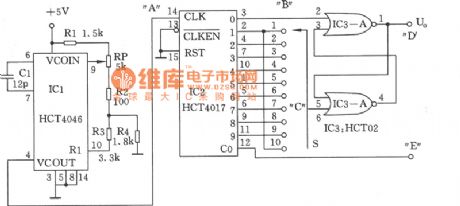
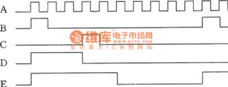
As shown in the figure, this circuit can provide adjustable square wave and rectangular wave generator 1.2KHz~2.7KHz work frequency, 10~90% duty cycle. The frequency comes form the voltage controlled oscillator and correlative components. The 1.2KHz~2.7KHz oscillation frequency is adjusted by potentiometer RP. The counter IC2 provides set pulse which form Q0 output to SR trigger IC3, the corresponding reset pulse is decided by Q1~Q9 output select switch S. The output frequency is 1/10 of IC2's input, the square wave is obtained form carry output C .
(View)
View full Circuit Diagram | Comments | Reading(1458)
Low power consumption wien bridge oscillator circuit diagram composed of MC1454
Published:2011/9/14 9:15:00 Author:nelly | Keyword: wien bridge oscillator
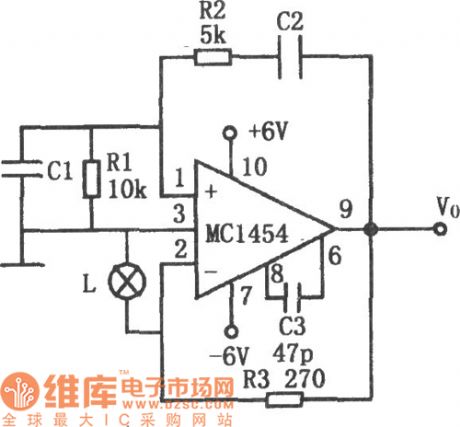
As shown in the figure, it is a low power consumption wien bridge oscillator circuit. When it drives low impedance and large capacitance loads, the distortion is small. The used operational amplifier can drive 8~10Ω loads, it can provide 2~4V peak value outout voltage, the frequency ranges from 1Hz to 100KHz, the distortion is lower than 0.5%. The automatic gain control is realized by bulb L, because the bulb's resistance changes in relation to the output voltage. The negative feedback circuit is composed of resistance R3, then it can determine the output signal amplitude.
(View)
View full Circuit Diagram | Comments | Reading(1182)
| Pages:482/2234 At 20481482483484485486487488489490491492493494495496497498499500Under 20 |
Circuit Categories
power supply circuit
Amplifier Circuit
Basic Circuit
LED and Light Circuit
Sensor Circuit
Signal Processing
Electrical Equipment Circuit
Control Circuit
Remote Control Circuit
A/D-D/A Converter Circuit
Audio Circuit
Measuring and Test Circuit
Communication Circuit
Computer-Related Circuit
555 Circuit
Automotive Circuit
Repairing Circuit