
Circuit Diagram
Index 485
BQ2058T charging and discharging protection device circuit
Published:2011/9/12 22:04:00 Author:John | Keyword: protection device
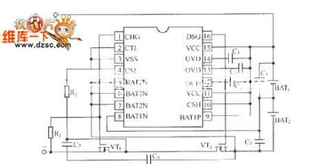
BQ2058 and BQ2058T / X are specifically for the series combination of lithium-ion battery. In the circuit, BQ2058T can achieve the connection of two lithium-ion batteries in series and BQ2058X can achieve the connection of three or four series Li-ion batteries. Extremely low operating current makes lithium-ion battery generator not over-discharge during storage. And the systematic effective discharge loads can not be increased. In the internal parts of the lithium-ion battery generator, BQ2058T / X is the part of the low-loss charge and discharge control and protection system. The BQ2058T discharging protection device is shown.
(View)
View full Circuit Diagram | Comments | Reading(1486)
RC Reset Circuit Connected to Schmitt trigger
Published:2011/9/13 0:06:00 Author:Zoey | Keyword: RC, Reset circuit, Schmitt trigger
The RC Reset circuit connected to Schmitt trigger has been presented in the picture below.When the power is poweredon and poweredoff repeatedly, circuir delay will prevent the power supply getting proper reset signal waveform. In fact, these two circuits are not used frequently. (View)
View full Circuit Diagram | Comments | Reading(879)
DS2760 lithium-ion battery protection circuit
Published:2011/9/12 22:04:00 Author:John | Keyword: lithium-ion battery

DS2760 has a 25mΩ sense resistor inside, which can detect two-way (charging and discharging) current (but its resistance and loss are bothe extremely small). The current resolution is 0.625mA and the dynamic range is within l.8A. It isalso with current cumulative function. The voltage measurement resolution is 48mV. Its temperature measurement resolution is up to 0.125 ℃. The digital converted by the A / D converter is stored in the corresponding memory container. It is connected with the main system through a single interface, thus leading it to be able to do management and control on lithium-ion battery power supply. Therefore, it is able to read / write access and control with internal memory container.
(View)
View full Circuit Diagram | Comments | Reading(2429)
SANLIXIN Intergrated Solenoid
Published:2011/7/11 7:58:00 Author:Michel | Keyword: Intergrated Solenoid
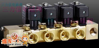
Welcome to download!This information is from www.dzsc.com. (View)
View full Circuit Diagram | Comments | Reading(765)
Anti-EMI Circuit
Published:2011/9/13 5:45:00 Author:Michel | Keyword: Anti-EMI

Theanti-EMI circuit is shown as above. MAX1703 is dc/dc boost converter, the input is 3.6 V, output is 5 V / 0.5 A.External random noise (PN) generating circuit provides the clock signal for 9 feet of the converter. In the wide frequency range, the PN generating circuit reduces EMI power density by extending interference frequency.PN generating circuit consists of 74HC164 and74HC74.74HC164 is eight shift register and it feedbacks through the different or a gate G1 and G2.PN signal is output by G2 and its rating frequency is 650kHZ and it is composed of repeatting 0 and 1 . The experimental measurement shows that frequency power density peak reduces to 15dB when it's around 300 kHZ and the efficiency of the converter remains unchanged except PN generating circuit adpots 9mA current from the converter. (View)
View full Circuit Diagram | Comments | Reading(694)
Circuit Diagram of Solar-energy Nickel-cadmium Cell Charger
Published:2011/9/12 23:47:00 Author:Zoey | Keyword: Solar-energy, Nickel-cadmium Cell, charger
The picture above shows circuit diagram of nickel-cadmium cell that uses solar energy.The solar panel can provide 6V voltage, LT1073 will detect charge current through the 13Ω resistor and willmaintain 16mA fixed charging current in the nickel-cadmiumcell.LT1073 will shut off the charging circuit when the output voltageon thesolar panelofthelow-voltage detector descends to 4V.When the voltageascends toabove 5V, the cell can be recharged again. (View)
View full Circuit Diagram | Comments | Reading(1222)
Two-road Output Voltage Regulating Circuit of LTC1702
Published:2011/9/13 5:44:00 Author:Michel | Keyword: Two-road Output, Voltage Regulating Circuit


The picture a and b are two-road output voltage regulating circuit of LTC1702.There are two independent switch power controllers in LTC1702 and each controller uses external N channel MOSFET as power switch.It uses as synchronous step-down voltage circuit of voltage feedback function and it is shown as picture (a).VD1 and C3 are charging pump circuit and it makes the power supply voltage rise.The switch frequency is set to 550 kHZ and user programmable current limiting circuit uses synchronization MOSFET switch tube VT2 as current sensitive components.But small external resistance of current sensitive resistance can not be used.The design of switch voltage regulating circuit is different from the ordinary circuit design's.LTC1702 uses accurate 25 MHZ bandwidth gain operational amplifier as feedback amplifier,which uses best loop circuit as the compensating plan.This plan can also improve loop response.
(View)
View full Circuit Diagram | Comments | Reading(650)
Meter-copy Device
Published:2011/9/13 5:51:00 Author:Michel | Keyword: Meter-copy

Micro meter-copy device changes electric meter into electrical signals via special camera images and it is transfered to LCD display via transmission lines.Special cameras and LCD monitor are connected together via adjustable aluminum alloy bars.Meter reading electrician can adjust aluminum alloy bars and make the top special cameras aim at electric meter so that he can see the electric meter degree in the bottom of the LCD monitor.Micro LCD visual meter-copy device isespecially designed according to the meter's measuring boxes. It consists of sunshades, adjustable auxiliary illuminant and iminiature camera etc.
(View)
View full Circuit Diagram | Comments | Reading(856)
LM1085 Low Voltage Margin Linearity and Stable Voltage Integrated Circuit
Published:2011/9/12 23:48:00 Author:Zoey | Keyword: Low voltage margin, linearity, stable voltage, integrated circuit,


LM1085 is a typical stable voltage integrated circuit that has low voltage margin and linearity. Its input voltage margin can be as low as 1.5v, and output current can be 3A.
LM1085 can input fixed voltage and also can adjust output voltage by exterior resistances. Encapsulation style ones are TO-220 and TO-263, which can be seen in the picture 1 and 2 respectively.
LM1085-ADJ belongs to input voltage and it can adjust integrated circuit of low voltage margin, the output ranges from 1.2~1.5V, which can be adjusted according to resistance value proportion of R1 to R2, as shown in picture 3.
In pratical, R1 is often fixed and R2 is adjustable. So, according to the formula:
Uo=VREF(1+R2/R1)+IADJR2
We can conclude following formula:
Uo=1.25 ·(1+R2/R1)
LM108x series have many types of integrated circuits, and their output current vary from one to another.
(View)
View full Circuit Diagram | Comments | Reading(0)
MAX8790 Typical Application Circuit
Published:2011/9/13 5:54:00 Author:Michel | Keyword: Typical, Application Circuit
MAX8790 is producedby MAXIM corporation of U.S.A .MAX8790 is designed for the white driving circuit which uses LED backlighting as the light source array LCD display (LCD) degsign.It uses the current model boost to drive 6 groups of LED and it can provide fixed 20mA or adjustable 15~25mA current to every group of LED.Current is adjusted by stepping control mode, each way current's precision can be controlled between about ±1.5%.
AX8790 can use DPWM (digital adjust way) or Analoge stats + DPWM (simulated adjusting mode of linear two ways) to adjust LED brightness。And the regulation range can reach 100∶1. (View)
View full Circuit Diagram | Comments | Reading(573)
Two Action Delay Relay LM122 Circuits
Published:2011/9/12 23:48:00 Author:Zoey | Keyword: Action Delay, Relay

LM122 is the time integrated block ranging from several microseconds to seconds. There is a reference voltage in LM122, and its voltage of power supply is ranging from 4.5 to 40V without changing the regular time.When the voltage on R/C terminal charges to 2V, the input transistor will turnover. When the timer works, the on-or-off problem can be solved by the logic terminal transistor input. Circuit(a) is a time delay power-on circuit and Circuit (b) is a time delay power-off circuit. (View)
View full Circuit Diagram | Comments | Reading(1107)
A Darlington Servo Circuit Diagram Driven by Operational Amplifier
Published:2011/9/12 23:49:00 Author:Zoey | Keyword: Darlington, Servo Circuit Diagram , Operational Amplifier
Following picture shows how operational amplifier drives the Darlington Servo circuit. This circuit carries and sets two power and voltage pins of 741, and then offers the two Darlington pipes margin input signals. From the statistic in the picture, we can see that the circuit can provide 30W’s power for 8Ωload. The input signal frequency can be as large as 100kHz. Circuit plus is 10 and circuit distortion is less than 0.2%.
(View)
View full Circuit Diagram | Comments | Reading(631)
the circuit of the constant temperature controller for fish breeding part1
Published:2011/9/12 21:49:00 Author:Ariel Wang | Keyword: constant temperature, controller, fish breeding

When the temperature of water is beyond the set temperature,the resistence of RT increases.It delays the time when VU outputs the trigger pulse in unit time.The conduction angle of VT decreases.The working voltage of EH decreases.The temperature of water decreases slowly.When the temperature of water is lower than the set temperature,VU outputs trigger pulse earlier.The conduction angle of VT increases.The working voltage of EH increases.The temperature of water goes up.It goes on and on.The water temperature of fish pool stays normal.
(View)
View full Circuit Diagram | Comments | Reading(832)
Circuitry Design for Electronic Lock, Sauna Lock, Cabinet Lock and Hotel Lock
Published:2011/9/12 23:50:00 Author:Zoey | Keyword: Electronic Lock, Sauna Lock, Cabinet Lock, Hotel Lock
Our company has always been concentrating on researching and developing a series of intelligentized, digitized and networked innovative products. Based on MCU Embedded technology, we have introduced methods of dealing with and controlling digital circuits, we have most systematic and strongest technology and application of digital circuits. By right of precious and scientific research and development, systematic test and experiment, we have mastered radiofrequency-series technology and attained corresponding independent intellectual rights. Regarding Electronic Technology as the kernel of our company, we observe the guideline of combining scientific research with industry, combing chip design with its application, we stand firmly on principle of Equality and Mutual Benefit, and redouble our efforts to offer our customers the best service. (View)
View full Circuit Diagram | Comments | Reading(933)
The driving circuit of the proportional electromagnet
Published:2011/9/12 21:50:00 Author:Ariel Wang | Keyword: driving, proportional electromagnet

If you want to control the circuit,you can change duty ratio which is input to electrical signal of proportional electromagnet switch to realize controlling electric current. The more place the duty ration takes ,the faster of the controlling electric current goes through the coil of electromagnet.And the larger of the displacement . See chart 1 for the proportional electromagnet driveing circuit.
In driving circuit,R1 is current limiting resistor .It conducts IRL tube.D1 is a steering diode. It provides the right voltage direction for IRL3803 tube. Diode D2 is being the protective role.It avoids over voltage destroy proportional electromagnet.Proportional electromagnet is charged directly by 24V voltage.
(View)
View full Circuit Diagram | Comments | Reading(710)
Inverter home electrotherapy
Published:2011/9/12 21:47:00 Author:Ariel Wang | Keyword: Inverter, home electrotherapy

The home electrotherapy has the the output frequency function of more than ten-speed automatic loop ransformation .The pulse intensity and the speed of the frequency conversion can be adjusted freely.It outputs a broad spectrum.The broad spectrum is very suitable to be as the massor .And it can dissipate fatigue and to be as an adjuvant treatment of some common diseases. The circuit consists of the variable frequency pulse oscillator, the oscillation frequency conversion controller and the pulse output circuit.
(View)
View full Circuit Diagram | Comments | Reading(2029)
Wiring Circuit of the Speaker
Published:2011/9/12 23:55:00 Author:Zoey | Keyword: Wiring Circuit, Speaker
Picture 20 shows the connection cable of the speaker, the connection cable uses a resistance that has small consumption and good response. Generally, speakers’ resistance is about several Ωto dozens Ω,and it is largely affected by power pinchoff produced by cable equivalent resistance. Therefore, the cable chose should have a low current resistance. In addition, frequency response of transportation signal is mainly determined by texture and material of the cable, the cable should be easily controlled by frequency response.
How to choose transistors and FET
Transistor circuits can be mainly divided into amplified circuit, switched circuit and oscillation circuit. Transistors available for these circuits are high frequency transistors, high amplifier factor transistors, high power transistors and general transistors.
General transistors: Japanese 2SA1048(UCEO=50V,Ic=150MA,Pc=200mW,hFE=70~400,T=80MHZ) and 2SC245(UCEO=5OV,Ic=15OMA,PC=2OOmW,hFE=70~700,T=80MHZ);Genral high frequency transitors: Japanese 2SC2668(UcEO=30V,Ic=2OmA,Pc=1OOmW,hFE=40~200,T=550MHZ) and 2SC3136(UCEO=20V,Ic=50mA,PC=250mW,hfe=40~300,T=1400KHZ);Genral crystal transitors: Japanese 2SA1516(UcEO=180V,IC=12A,Pc=130W,hFE=55~180,T=25MHZ) and 2SC3907(UCEO=180V,Ic=12A,PC=130W,hFE=55~180,T=30MHZ);
Genral dual transitors:Japanese 2SA1349(UCEO=80V,Ic=100MA,Pc=200mWx2,hFE=200~700)and 2SC3381(VCEO=80V,IC=1OOMA,Pc=200x2mW,hFE=200~700)。Chinese low power low frequency transistors:3AX、3BX、3CX、3DX series. General FET:2SJ105(UGDS=5OV,IDSS=1.2~1.4mA,PD=2OOmW,Ciss=18pF) and 2SK330(UGDS=5OV,IDSS=1.2~1.4mA,PD=2OOmW,CISS=9pF);High frequency FET:2SK241(UGDS=2OV,IDSS=1.5~14mA,PD=2OOmW,Ciss=3pF);Power FET: 2SJ200(UGDS=180V,IDSS=1OA,PD=12OW,CiSS=1300pF) and 2SK1529(UGDS=180V,IDSS=1OA,PD=12OW,Cis=700pF);Dual tubes:2SJ109(UGDS=30V,IDSS=2.6~2OmA,PD=2OOmW,Ciss=95pF) and 2SK389(UGDS=5OV,IDSS=2.6~2OmA,PD=2OOmW,Ciss=25pF)。 (View)
View full Circuit Diagram | Comments | Reading(1419)
Integrated Circuit of High-fidelity Dual Track Amplifier TDA2616
Published:2011/9/12 23:57:00 Author:Zoey | Keyword: Integrated Circuit, High-fidelity, Dual Track, Amplifier
1.Circuit Diagram and pin function of TDA2611A
TDA2616 is used as power amplifiers in TV sounders, compound sounders and active sounders.
There are two identical audio frequency amplified circuits in TDA2616 integrated block. Its integrated block interior circuit and dual power supply circuit have been presented in the picture. In this IC, pin 9 is single inline encapsulation, pin function and statistics have been presented in the chart.
2 Main parameters of TDA2616
(1) Dual power supply. If Vcc=±16V, R(l)=8Ω,THD=0.5%,Po=12W. If THD=10%,Po=15W.
(2)Single power supply. If Vcc=24V, THD=10%, if R(l)=4Ω, Po=14W.
3 Typically-applied Circuit of TDA 2616. As shown in picture, they refer to TDA dual power supply circuit and integrated block single power supply circuit respectively.
4 Malfunction Examination and repair alert
Whether it is a single supply or dual power supply, when there is a silent failure, we should firstfigure ourifthe squelch circuit isin the wrong starting state. We canjudge the statebycutting off pin 2.
(View)
View full Circuit Diagram | Comments | Reading(861)
Anti-toll-fraud sound and light annunciator circuit diagram
Published:2011/9/13 6:48:00 Author:Vicky | Keyword: anti-toll-fraud, sound and light annunciator circuit
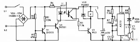
Anti-toll-fraud sound and light annunciator circuit diagram is shown in the above picture. The picture is an anti-toll-fraud sound and light warning circuit. It is assembled in the junction box of service entrance conductor. It normally does not consume power or affect the normal work of telephone. When anyone uses the line to make calls stealthily, the luminous diode shrinks, and the annunciator sound sends out warning. Because the voltage of the exterior line of the telephone is higher, the diode VD1~VD4 adopts 1N4004 type diode. Triode V1 and V2 use small-power high reverse voltage tube, such as types (PNP type, note that the polarity of the power supply should be changed) of 2N5551 (it’s reverse voltage is 160V) or 2N5401. The relay K adopts 4098 of small size, and the work voltage uses 3V. (View)
View full Circuit Diagram | Comments | Reading(2326)
LM101A and LM108 high-speed integrator circuit diagram
Published:2011/9/13 6:49:00 Author:Vicky | Keyword: high-speed integrator circuit

The above picture is a high-speed integrator circuit. The integration time constant RtCt in the circuit has a wide range of changing. In regardless of integration capacitance Ct, A2 is a broadband AC amplifier of positive and negative compensation. When capacitance Ct is added to the negative feedback circuit of A2, then the integrator comes into being. Because the low frequency and DC part of input signal are added to the non-inverting input end of A2 via A1 and resistance R2 respectively, the high-speed integrator then is formed, and it allows relatively low input bias current. Positive and negative compensation is composed of R4, C4 and C5. (View)
View full Circuit Diagram | Comments | Reading(1427)
| Pages:485/2234 At 20481482483484485486487488489490491492493494495496497498499500Under 20 |
Circuit Categories
power supply circuit
Amplifier Circuit
Basic Circuit
LED and Light Circuit
Sensor Circuit
Signal Processing
Electrical Equipment Circuit
Control Circuit
Remote Control Circuit
A/D-D/A Converter Circuit
Audio Circuit
Measuring and Test Circuit
Communication Circuit
Computer-Related Circuit
555 Circuit
Automotive Circuit
Repairing Circuit