
Circuit Diagram
Index 501
Single-chip RF Power Measurement System MAX2015-made RF Power Control System Circuit
Published:2011/5/16 20:40:00 Author:Sharon | Keyword: Single-chip, RF Power Measurement, Power Control System

What shows in the figure is the RF power control system circuit formed by single-chip RF power measurement system MAX2015. The set point voltage USET provided by D / A converter (DAC) is linked to the SET side of MAX2015. RF signals emitted by the antenna pass through the coupler to the input of MAX2015. MAX2015's output voltage Uo acts as input signal of the variable gain amplifier and is used to control the transmission power. (View)
View full Circuit Diagram | Comments | Reading(1042)
Lead accumulator charger circuit diagram
Published:2011/9/7 6:54:00 Author:Vicky | Keyword: Lead accumulator charger circuit

Lead accumulator charger circuit is shown in the above picture. The charger adopts constant voltage type charging. It controls the end of charging by the reduction of the charging current brought by the gradually adequate battery power. There is no need to worry about over-charging or lack of charging. When the power is on, the level of U1A inverting end , pin2, is always lower than the non-inverting input end, pin3. Therefore, pin 1 of U1A outputs high level, which makes Q1 saturate and conducted. It is as effective as the grounding of pin ADJ of U2, and the output of U2 is 1.2V with the charging end of 0.6A. It presents light load under such circumstance, and DS2 green luminous diodes is lighted. When the button S2 is pressed down, pin3 of U1A is grounded, pin2 is connected with the positive pole of the power via R1, then the U1A outputs low level, DS2 red luminous diode is lighted, and DS1 goes out. (View)
View full Circuit Diagram | Comments | Reading(2197)
Lead-acid cell over-charging protector circuit diagram
Published:2011/9/7 6:56:00 Author:Vicky | Keyword: lead-acid cell , over-charging protector circuit

Lead-acid cell over-charging protector circuit is shown in the above picture. The protector can prevent middle size or large size lead-acid cell with capacity between 2 and 30 Ah from over-charging in the process of floating charging (the cell provides power for the load while being charged by trickle charge or solar panel). When it is not in the process of charging, Q1 cannot conduct the electricity due to the impedance of D1. When the charging voltage rises to about 14V, transistor Q1 (2N3055) is conducted, and splits the battery current to prevent the electrolyte from evaporating, which is beneficial for heat dissipation. Q1 should be assembled in a medium size heating panel. NTE143A can be also play the role of Q1. (View)
View full Circuit Diagram | Comments | Reading(2670)
Vehicle nickel-cadmium battery charger circuit diagram
Published:2011/9/7 6:58:00 Author:Vicky | Keyword: vehicle nickel-cadmium battery charger circuit

Vehicle nickel-cadmium battery charger circuit is shown in the above picture. It makes use of NE555 timer and two voltage multiplier circuits composed of power transistor so as to convert the voltage of vehicle battery from 12V to above 20V and then charge the 12V nickel-cadmium battery without changing the current. The voltage which has been multiplied sends the power current to three-end current stabilizer. NE555 are connected and form multi-vibrator, and the switch frequency is 1.4KHz. The charging current is set at 50mA, which can charge 10 pieces of 500mA·h nickel-cadmium batteries. (View)
View full Circuit Diagram | Comments | Reading(2238)
Measuring Triac circuit diagram with digital multimeter
Published:2011/9/7 21:38:00 Author:Lucas | Keyword: Measuring Triac , digital multimeter

The chart shows the digital multimeter measuring circuit. When it is appropriated to NPN file, then the G base of Triac VT is open and connected to C hole of hFE socket by a current limiting resistor R (330Ω or so), T1 is inserted into the E hole by wires. Resistor R here is used to prevent hFE circuit overload, and at this time, digital multimeter display is 000 , that is the off stste, then the G pole and T2 are in short connection by wires, then digital multimeter jumps immediately to 578 , which explains that it had turned. The right figure is the Triac double passing validation circuit.
(View)
View full Circuit Diagram | Comments | Reading(1605)
Underarm odor therapeutic apparatus circuit diagram
Published:2011/9/8 3:23:00 Author:Lucas | Keyword: Underarm odor, therapeutic apparatus
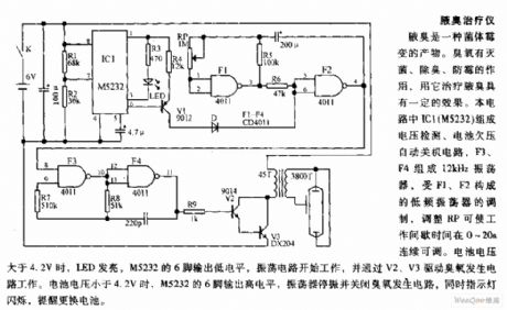
Underarm odor is a product of bacterial mildew. Ozone has the functions of sterilization, anti-odor, anti-mold and anti-mildew, and it has some specific treatment effect for underarm odor. In the circuit, IC1 (M5232) forms the voltage detection, battery undervoltage auto shutdown circuit, and F3, F4 form the 12kHz oscillator, which is modulated by the low-frequency oscillator composed of F1, F2, and adjusting RP can make work interval be continuously adjustable at 0 ~ 20S. When the battery voltage is greater than 4.2V, LED is lit, and M5232's pin 6 outputs low, then the oscillator works to drive ozone circuit by V2, V3.
(View)
View full Circuit Diagram | Comments | Reading(1775)
ECG telemetering circuit diagram
Published:2011/9/7 2:43:00 Author:Lucas | Keyword: ECG telemetering

The circuit is designed for experimental or teaching, and it can be used to hear the ECG signal voltage. ECG signal voltage is amplified by the LM4250 op amp for modulating the NE566, which is connected as voltage-controlled oscillator, and oscillator output is used to drive small speakers, so you can hear the ECG signal. If you want to telemetry, you can use the microphone to pick up the sound output. In order to connect the circuit and the patient, you can use standard adhesive monitoring electrodes, you can also use a small piece of metal to tie to the patient's wrist by rubber.
(View)
View full Circuit Diagram | Comments | Reading(1878)
Mini rhythm tester circuit diagram
Published:2011/9/7 3:11:00 Author:Lucas | Keyword: Mini rhythm tester

HTD receives heart beat signal, then it is amplified by F1, F2. R4, C3 are used to filter out high frequency signal, then it is input F7 afeter amplifing by F3, F4, shaping by F5, F6. F7 and the peripheral circuitform the monostable circuit, so it gets positive pulse signal with the frequency being the same with heart rate at the F8 output end ( pulse width is 40ms). DW, RP, V, P form the constant current circuit, and it will get a pulse current in P of the meter, then it is integrated by C8 to make the faster heart rate and greater P display. In the contrary, the rate and display is smaller.
(View)
View full Circuit Diagram | Comments | Reading(1136)
Multi-color projector circuit diagram for nerve relaxation
Published:2011/9/8 3:37:00 Author:Lucas | Keyword: Multi-color projector , nerve relaxation
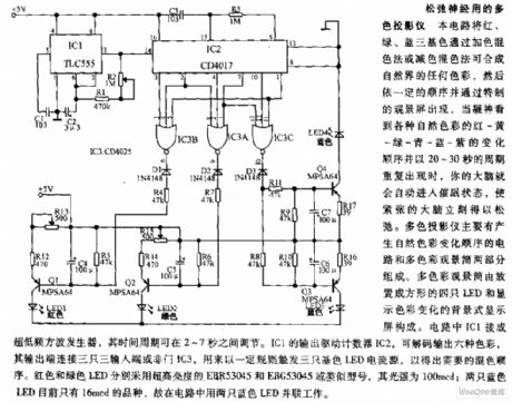
The circuit can mix red,green, blue in any color in nature by additive color mixing method or subtractive color mixing method, then they appears as the special viewing screen in a certain order. When your breath to see a variety of natural colors: red - yellow - green - green - blue - purple and the order changes in 20 to 30 seconds and repeats in the cycle, then your brain will automatically enter the hypnotic state, the tension of the brain is immediately relaxed. Multicolor projector is composed of the circuit which generates natural color changing order and multi-color viewing tube.
(View)
View full Circuit Diagram | Comments | Reading(2299)
Dual-output electronic ballast circuit diagram
Published:2011/9/7 22:19:00 Author:Lucas | Keyword: Dual-output electronic ballast
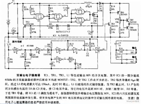
IC1, TR1, TR2, L1 form the switching power supply with output in 80V. One part of IC1 forms the 65kHz square wave oscillator to drive N-channel MOSFET-TR2 after buffering, then TR2 works in the switching state. During each 8μs turning time of TR2, L1's passing current is up to 150mA, at this time, D3 closes, and L1 stores energy in the magnetic field, when the TR2 stops, L1's induced current charges to C3 by the D3, then the C3 voltage increases. When its voltage rises to 80V, the zener diodes D1, D2 are conduction. So TR1 is turned on. Then IC1's pin 13 is in low level.
(View)
View full Circuit Diagram | Comments | Reading(2752)
Adjustable speed LED flasher circuit diagram
Published:2011/8/30 20:26:00 Author:Lucas | Keyword: Adjustable speed, LED flasher
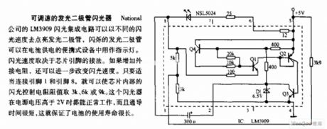
National's LM3909 flashing IC flash can light the light-emitting diode in different rates, and the flashing LED is used as indicator in the battery-powered portable devices. Flashing speed depends on the chip pin connection. If it increases an external resistor, the flashing rate can be further improved. If the connection of pin 1 and pin 8 is appropriately, you can make the chip internal controlling resistor take 3K, 6K, or 9K. The flashing device can work normally with the power supply voltage higher than 2V, but the lead time is very short, which ensures long battery life.
(View)
View full Circuit Diagram | Comments | Reading(1676)
Using the PWM3 terminal of the intelligent remote hot fan controller ADT7460 to drive two three-wire fan
Published:2011/9/8 3:25:00 Author:Felicity | Keyword: PWM3 terminal, intelligent remote hot fan controller , three-wire fan


Using transistors:
Using FET:
(View)
View full Circuit Diagram | Comments | Reading(735)
The electronic thermometer circuit diagram for blind
Published:2011/9/8 2:57:00 Author:Lucas | Keyword: electronic thermometer, blind
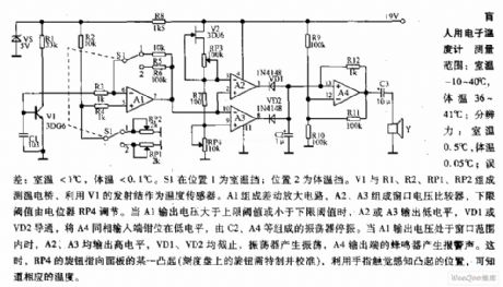
Measuring range: room temperature is -10 ~ 40 ℃; body temperature is 36 ~ 41 ℃; Resolution: room temperature is 0.5 ℃, body temperature is 0.05 ℃; error: room temperature <1 ℃, body temperature <0.1 ℃. When S1 is in position 1, it shows the room temperature profile; position 2 is the body temperature profile. V1, R1, R2, RP1, RP2 form the temperature testing bridge, which uses the V1 emitter junction as a temperature sensor. A1 forms the differential amplifier, and A2, A3 form the window voltage comparator, and the lower threshold is adjusted by the potentiometer RP4. When A1 output voltage is greater than the upper threshold or less than the lower threshold, A2 or A3 outputs low, VD1 or VD2 is conduction, then the inverting input of A4 is located in the embedded low level.
(View)
View full Circuit Diagram | Comments | Reading(2098)
Circuit diagram of charger with diminishing pulse charging current exponentially
Published:2011/9/7 7:04:00 Author:Vicky | Keyword: charger, diminishing pulse charging current exponentially

Circuit diagram of charger with diminishing pulse charging current in accordance with index is shown in the above picture. A1 and A2 constitute controlled multi-vibrator. Set the threshold value at around 1.45V. Back electromotive force generated by the polarized electric fields of the battery during charging would directly influence the output state of A2. During the test, when conducting pulse charging to the current, the increasing and decreasing speed of the polarized electric field strength and the depth of electrochemical reaction inside the battery present exponentially changing. The circuit utilizes this discipline to regulate the frequency and pulse brand of the pulse charging current and to realize the goal of controlling.
(View)
View full Circuit Diagram | Comments | Reading(2128)
Automatic voice greeting circuit diagram
Published:2011/9/7 1:56:00 Author:Lucas | Keyword: Automatic voice greeting
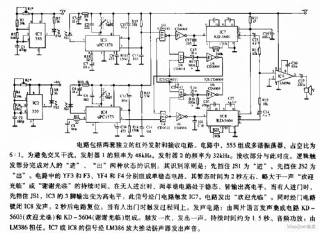
The circuit consists of two separate infrared transmitter and receiver circuits. In the circuit, 555 forms the multivibrator, and the duty cycle is 6:1. In order to avoid cross-infection, the frequency of the transmitter 1 is 48kHz, and the frequency of the transmitter 2 is 32kHz. Sound circuit consists of two voice integrated circuits KD5603 (Welcome) and KD-5604 (Thank you for coming). It is triggered once to emit sound. And the duration is 1.5 S. The audio amplifier is played by the LM386. IC7 and IC8's signal is amplified by LM386 to drive the speaker and emit sound.
(View)
View full Circuit Diagram | Comments | Reading(1146)
Wireless two-tone electronic doorbell circuit diagram
Published:2011/9/7 22:08:00 Author:Lucas | Keyword: Wireless two-tone, electronic doorbell

Transmitter: Pressing the SB will make the transmitter circuit work. D1, D2 and R2, R3, C4 constitute a low-frequency oscillator to control the audio oscillator composed of the D3, D4 and D5, D6, then it works alternately. The generated audio signal is added to modulation side of Rf signal oscillator by C7. Then high-frequency oscillator signal is sent to air after modulation. Receiver circuit: frequency-modulated wavesensed by the antenna is demodulated by A2, then its pin 14 outputs two-tone doorbell signal, which is coupled to the input of A3 by R7, C26, while the pin 9 outputs low so that switch V2 is conduction, then A3 gets power and works.
(View)
View full Circuit Diagram | Comments | Reading(4805)
Circuit diagram of prolonging the lifetime of nickel-cadmium battery
Published:2011/9/7 7:00:00 Author:Vicky | Keyword: nickel-cadmium battery, prolonging the lifetime

Circuit diagram of prolonging the lifetime of nickel-cadmium
Generally, the voltage of a single nickel-cadmium battery is 1.2V. 6V or 9v nickel-cadmium battery sold in the market now is in fact made of 5 or 8 nickel-cadmium battery of 1.2V in serial. Experience suggests that the lifetime of a battery can be prolonged when it was charged with still 1V left. Generally speaking, a battery should not be used when there is 1~1.1V left. The battery voltage must be reduced to 1V before charging, and the best discharging current is 100mA. The circuit in the picture can realize the above function. Take 6V battery as an example. When the battery voltage reduces to 5V, output voltage of IC1 provides the reference DC voltage of 1.25V for inverting input end of IC2 by voltage divider composed by R4 and R5. The reference voltage is higher than the divided voltage of R2 and R3. IC2 outputs low level which stops G, and the discharging stops. When the voltage of battery E is higher than 5V, IC3 outputs high level, and makes LED lighted, G conducted, and battery discharges via R7. (View)
View full Circuit Diagram | Comments | Reading(1171)
SCR flashing LED circuit diagram
Published:2011/9/5 3:20:00 Author:Lucas | Keyword: SCR flashing LED
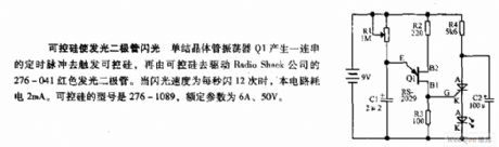
Single-junction transistor oscillator Q1 produces a series of timing pulses to trigger the SCR, then the SCR drives the 276-041 red light-emitting diode produced by Radio Shack company. When the flashing rate is 12 times per second, the circuit power consumption is 2mA. SCR model is 276-1089, ratings are 6A, 50V.
(View)
View full Circuit Diagram | Comments | Reading(1112)
Pressure monitoring system composed of intelligent sensor signal processor MAX1460 and silicon pressure sensor
Published:2011/9/7 2:50:00 Author:Lucas | Keyword: Pressure monitoring system, intelligent sensor, signal processor , silicon pressure sensor


The system uses the +5 V supply, and the crystal frequency is 2MHz. R1 and R2 form the power divider, and the analog ground (AGND) is on the midpoint of the power supply. C is the power supply decoupling capacitor. Host can use PC, and the host firstly tests MAX1460 and receives 12-bit parallel data output by MAX1460, then it moves out the testing system, and MAX1460 and the sensor form a high-precision intelligent pressure monitoring system, and the conversion rate is 15 times / sec, the measurement error is less than ± 0.1%. In the Figure, the FSO is the full-scale, OFFSET is the disorder, γ indicates the relative error at full scale.
(View)
View full Circuit Diagram | Comments | Reading(836)
Light-operated aquarium flashing light circuit diagram
Published:2011/9/7 2:33:00 Author:Lucas | Keyword: Light-operated aquarium , flashing light
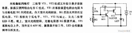
Transistors VT1, VT2 form the complementary self-excited multivibrator, and the oscillator feedback network is composed of the capacitor C. The base bias circuit of VT1 consists of resistor R and the photosensitive resistor RG. Indoor light is strong during the day, RG is exposed to strong light shows low resistance, VT1 base is in low level, VT1, VT2 are closed, light-emitting diode LED is not lit. At night, indoor light is weak, the photosensitive resistor RG is increased, VT1's base potential rises, when it rises to 0.65V, the oscillator starts to work, LED light will flash according to the oscillation frequency.
(View)
View full Circuit Diagram | Comments | Reading(1043)
| Pages:501/2234 At 20501502503504505506507508509510511512513514515516517518519520Under 20 |
Circuit Categories
power supply circuit
Amplifier Circuit
Basic Circuit
LED and Light Circuit
Sensor Circuit
Signal Processing
Electrical Equipment Circuit
Control Circuit
Remote Control Circuit
A/D-D/A Converter Circuit
Audio Circuit
Measuring and Test Circuit
Communication Circuit
Computer-Related Circuit
555 Circuit
Automotive Circuit
Repairing Circuit