Electrical Equipment Circuit
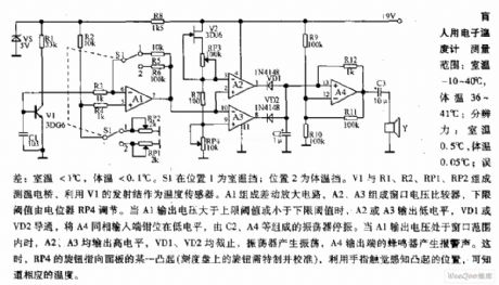
The electronic thermometer circuit diagram for blind
Published:2011/9/8 2:57:00 Author:Lucas | Keyword: electronic thermometer, blind | From:SeekIC

Measuring range: room temperature is -10 ~ 40 ℃; body temperature is 36 ~ 41 ℃; Resolution: room temperature is 0.5 ℃, body temperature is 0.05 ℃; error: room temperature <1 ℃, body temperature <0.1 ℃. When S1 is in position 1, it shows the room temperature profile; position 2 is the body temperature profile. V1, R1, R2, RP1, RP2 form the temperature testing bridge, which uses the V1 emitter junction as a temperature sensor. A1 forms the differential amplifier, and A2, A3 form the window voltage comparator, and the lower threshold is adjusted by the potentiometer RP4. When A1 output voltage is greater than the upper threshold or less than the lower threshold, A2 or A3 outputs low, VD1 or VD2 is conduction, then the inverting input of A4 is located in the embedded low level.
Reprinted Url Of This Article:
http://www.seekic.com/circuit_diagram/Electrical_Equipment_Circuit/The_electronic_thermometer_circuit_diagram_for_blind.html
Print this Page | Comments | Reading(3)

Article Categories
power supply circuit
Amplifier Circuit
Basic Circuit
LED and Light Circuit
Sensor Circuit
Signal Processing
Electrical Equipment Circuit
Control Circuit
Remote Control Circuit
A/D-D/A Converter Circuit
Audio Circuit
Measuring and Test Circuit
Communication Circuit
Computer-Related Circuit
555 Circuit
Automotive Circuit
Repairing Circuit
Code: