Electrical Equipment Circuit
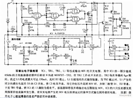
Dual-output electronic ballast circuit diagram
Published:2011/9/7 22:19:00 Author:Lucas | Keyword: Dual-output electronic ballast | From:SeekIC

IC1, TR1, TR2, L1 form the switching power supply with output in 80V. One part of IC1 forms the 65kHz square wave oscillator to drive N-channel MOSFET-TR2 after buffering, then TR2 works in the switching state. During each 8μs turning time of TR2, L1's passing current is up to 150mA, at this time, D3 closes, and L1 stores energy in the magnetic field, when the TR2 stops, L1's induced current charges to C3 by the D3, then the C3 voltage increases. When its voltage rises to 80V, the zener diodes D1, D2 are conduction. So TR1 is turned on. Then IC1's pin 13 is in low level.
Reprinted Url Of This Article:
http://www.seekic.com/circuit_diagram/Electrical_Equipment_Circuit/Dual_output_electronic_ballast_circuit_diagram.html
Print this Page | Comments | Reading(3)

Article Categories
power supply circuit
Amplifier Circuit
Basic Circuit
LED and Light Circuit
Sensor Circuit
Signal Processing
Electrical Equipment Circuit
Control Circuit
Remote Control Circuit
A/D-D/A Converter Circuit
Audio Circuit
Measuring and Test Circuit
Communication Circuit
Computer-Related Circuit
555 Circuit
Automotive Circuit
Repairing Circuit
Code: