
Circuit Diagram
Index 509
Full-bridge power conversion circuit
Published:2011/8/31 2:25:00 Author:John | Keyword: Full-bridge power conversion

When high power output is needed, full-bridge power conversion circuit is generally used. The figure shows the full-bridge power conversion circuit. As pointed out above, power transistor in the half-bridge power conversion circuit can withstand a maximum voltage which is half of that in the push-pull working transistor. However, if the output power requirements are of the same, the working current for the transistor will increase greatly. Full-bridge power conversion circuit has both advantages of those two circuits. It is able to maintain the power switching devices bearing down just like a half-bridge circuit, and it is also able to have small current-carrying characteristics just like a push-pull circuit.
(View)
View full Circuit Diagram | Comments | Reading(1082)
CMOS operational amplifier drive circuit
Published:2011/8/31 2:17:00 Author:John | Keyword: CMOS operational amplifier

Figure shows the CMOS operational amplifier drive circuit. As the output current of CMOS operational amplifier is generally small, a few blocks of CMOS operational amplifiers should be set in parallel for driving the LED, as shown in Figure (a) and Figure (b). Sometimes, a CMOS operational amplifier transistor can be added to extend the drive current, as shown in Figure (c). In the circuit shown in Figure (d), once driven, CMOS operational amplifier’s output voltage can be incurred by LED clamp around the UF.
(View)
View full Circuit Diagram | Comments | Reading(701)
CUK power conversion circuit
Published:2011/8/31 2:01:00 Author:John | Keyword: power conversion

It is obvious to find that the three power conversion circuits described above have a common characteristic. Excluding the role of output capacitor, inductance is only needed to transfer energy storage inside people to the load in switching process by the power switching devices. Thus, they are all belonging to the inductive power conversion circuit. Different combinations of the capacitor and diode can also achieve three kinds of circuits which are featured of buck, boost, polarity inversion. They are also called the so-called capacitive energy transfer power conversion circuit. The principle circuit is as shown.
(View)
View full Circuit Diagram | Comments | Reading(609)
smart humidity gauge constituted by the humidity sensor and the microprocessor circuit
Published:2011/8/31 1:52:00 Author:John | Keyword: smart humidity gauge, humidity sensor, microprocessor

PIC16F874 has a wide range of supply voltage (+2.5 ~ +5 V), which is suitable for low voltage power supply. The quiescent current is less than 2mA. The RA port (RA0 ~ RA7) is the I / O interface. And the PA0 (also known as AIN0) port line is used to receive the voltage signal generated by the humidity sensor. Output bit PA1 ~ PA4 scans signal and receives inverting-phase drive signal through MC1413. Section between RB0 and RB6 of the RB port outputs 7-segment signal. And then the corresponding pen electrodes of LED display is within a ~ g. PIC16F874 also features of power-down protection. And MCLR reset the latch for the power-down side.
(View)
View full Circuit Diagram | Comments | Reading(1065)
Low-cost Dual Output Regulator Circuit Composed Of MIC29152-12 And MIC29150-5.0
Published:2011/8/11 8:37:00 Author:Felicity | Keyword: Low-cost, Dual Output, Regulator

View full Circuit Diagram | Comments | Reading(1057)
The photo control electric switch
Published:2011/9/5 22:50:00 Author:Seven | Keyword: photo control, electric switch

Working principles: see as the figure, after the 220V AC passes the bulb H and the rectifier bridge, it becomes the DC pulse voltage as the forward biased voltage, which can be added on the SCR VS and branch R. In daylight, when the brightness is over some degree, the LDR D is in a low resistance which is ≤1KΩ, so the triode V is blocked and there is no current out from it, the single way SCR VS is blocked due to the lack of trigger current. At the moment, the current past bulb H is ≤2.2mA, the bulb is not glowing. (View)
View full Circuit Diagram | Comments | Reading(953)
The connector circuit with 2 lines of SI intelligent temperature sensor TCN75 and 89C51
Published:2011/8/23 22:41:00 Author:qqtang | Keyword: temperature sensor, connector circuit
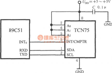
The connector circuit of TCN and 89C51 is shown in the circuit. All the address input terminals A2~A0 of TCN75 are connected with the high LEV UDD, the address code is set to be 111. 89C51 fulfills the selective function with the software. The 89C51 serial data collecting terminal (RXD) and the serial data emitter(TXD) are linked to SDA and SCL of TCN75. The halt/compare signal of TCN75 is linked to the halt terminal INT0 of 89C51.
(View)
View full Circuit Diagram | Comments | Reading(581)
The gain programmable instrument amplifier composed of INA102
Published:2011/8/13 3:11:00 Author:qqtang | Keyword: gain, programmable, instrument amplifier

View full Circuit Diagram | Comments | Reading(733)
The long-distance temperature test circuit composed of intelligent warm air fan controller ADT7460
Published:2011/8/23 22:41:00 Author:qqtang | Keyword: temperature test, warm air, fan controller

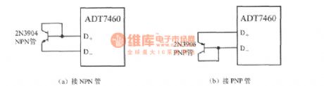
ADT7460 is coupled with 2 long-distance temperature sensors consisting of transistors, it measures distance temperature by using the feature that the transistor emitting knot voltage (UBE) is in forward proportion with temperature. The circuit is shown in the figure. In the figure, the CPU itself is taking a temperature test transistor with it, which is equal to a PNP transistor of 2N3906 type. If a separated transistor is used, the collecting electrode can not connect with the earth, but link with the base electrode as the diode. When using NPN transistor, we should connect the base electrode with terminal D+ and emitter with terminal D.
(View)
View full Circuit Diagram | Comments | Reading(569)
the portable hearing aid
Published:2011/8/23 23:47:00 Author:Ariel Wang | Keyword: portable, hearing aid

The capacitor C3 is used to weaken the high frequency in earphone BE.C4 is the power supply filter capacitor.RP is the potentiometer for volume control.The audio signal from the microphone BM is multi amplified by the hearing aid application specific integrated circuit TB5318.Then it drives the earphone BE to play.As the in-circuit IC1's gain is high,you should pay attention to the layout and routing of the whole machine component.It is to avoid self-excitation.The value selection of the resistance R's pin② of IC1 has something to do with the integrated circuit Sub-block value.You should select it within the range of 360kΩ~1MΩ.BE should adopt high-resistance earphone.
(View)
View full Circuit Diagram | Comments | Reading(2715)
the music hypnosis
Published:2011/8/24 0:08:00 Author:Ariel Wang | Keyword: music, hypnosis

When the switch button SB gets through,C1 is charging.VT1 and VT2 are conducted.When SB is disconnected,VT1 and VT2 could stay conducted as C1 discharges to VT1 by RP1 and R1.VT3 is conducted because it gains forward biased current from polar c and e of VT2 through diode VD.IC1 works.The pin③ outputs music signal.The signal is amplified by VT4,then it drives the horn to give out a sound.The horn will play the music on and on in certain time as the pin② of IC1's trigger end connects to the positive electrode.In this way,it reaches the goal of hypnosis.The playing speed is adjusted by RP3.
(View)
View full Circuit Diagram | Comments | Reading(530)
The effective ozone generator
Published:2011/8/24 0:43:00 Author:Ariel Wang | Keyword: effective, ozone generator

The ozone is a strong oxidizer.It has the ability to sterilize,bleach,deodorize and oxygenate.The specific circuit of the effective ozone generator is shown as the chart.The power transformer outputs +12V voltage time-base provides power supply to the integrated circuit 555 and ozone generater component ND-120A after it is commutated.IC1,R1 and C2 made up the monostable oscillator.You can adjust the value of R1 and C2 to change the oscillation frequency of IC1.The pin③ outputs oscillation impulse after IC1 oscillates.It stimulates ozone components.Then the pin④ and pin⑤ drive the ozone chips directly.The circuit can generate 100~150mg ozone every hour.It could be used in the place with low ozone density.
(View)
View full Circuit Diagram | Comments | Reading(4990)
The electric biological wave physiotherapy
Published:2011/8/24 0:42:00 Author:Ariel Wang | Keyword: electric, biological wave, physiotherapy

The electric biological wave physiotherapy circuit is shown as the chart.It can generate the electric signals of various composite frequency.It is good for the drugs absorption for the patients.It can also act on the human acupoint to do the treatment.
(View)
View full Circuit Diagram | Comments | Reading(1002)
the high sensitivity demonstration ammeter
Published:2011/8/25 23:09:00 Author:Ariel Wang | Keyword: high sensitivity , demonstration ammeter

The ammeter could be applied for the experiments below:the Ohm law in closed circuit;the current distribution and amplification of the transistor;through the experiment,you can try to find the resistance of metal conducting wire and the length of the conducting wire,the relationship between the cross section area and the material,the relationship between the circuit voltage and the external resistance,the relationship between the series connection and parallel connection,the resistance measurement by using the voltammetric method,the electromotive force and resistance measurement by using the ammeter and the voltmeter and whether it generates induced current by single wire cutting of flux.The principle of the high sensitivity demonstration ammeter is seen as the chart. (View)
View full Circuit Diagram | Comments | Reading(842)
The simple consumption meter
Published:2011/8/25 23:15:00 Author:Ariel Wang | Keyword: simple, consumption meter

The simple consumption meter is made up of the sensor,the logic controller,the pulse generator and the swiching module.The circuit is seen as the chart.
(View)
View full Circuit Diagram | Comments | Reading(707)
the high precision region voltmeter
Published:2011/8/26 6:43:00 Author:Ariel Wang | Keyword: high precision , region voltmeter

The circuit adopts the amplifier and high precision components.It improves the performance of the region voltmeter greatly.The inverting input of IC2 meter amplifier AD623 uses the high precision voltmeter reference IC1 as a standard.The noninverting input ends R1,RP1 and R3 enlarge the voltmeter to be measured.RP1 is the zero potentiometer .RP2 is the gain adjustment potentiometer.The amplifier output end is enlarged by the branched resistance R4.Then it connects the table head with the starting value and the termination value.You can select a region of voltmeter Vin to be measured.The starting value is V1.The termination value is V2.The voltmeter Vin to be measured changes within the range of V1~V2.
(View)
View full Circuit Diagram | Comments | Reading(1484)
The phase detection circuit
Published:2011/8/26 19:35:00 Author:Ariel Wang | Keyword: phase, detection

The phase detection circuit is made up of IC1(voltage comparator LM319) and IC2(double D trigger C013).The circuit has the advantages of simle struction,high precision and strong anti-jamming ability.Within the range of 0~30kHz,the detection precision is better than 0.1o.The output signal of the circuit could connect to the computer interface directly,and it can also connect to the digital voltmeter by low-pass filter.In this way,it forms the ideal phase detector.
(View)
View full Circuit Diagram | Comments | Reading(1188)
the reflect meter circuit composed of monolithic broadband phase-difference measurement system AD8302
Published:2011/8/26 19:58:00 Author:Ariel Wang | Keyword: reflect meter , monolithic, broadband, phase-difference

It is the reflect meter circuit composed of monolithic broadband phase-difference measurement system AD8302.You can work out at the reflection coefficient y by measuring the incident load signal and the gain of the reflected signal from the load.The calculation formula of the reflection coefficient is:y=the reflected voltage/the incident voltage=(ZL-ZO)/(ZL+ZO).In the formula,ZL represents the load impedance by using the complex number.ZO is the characteristic impedance in the system.The reflection coefficient is used to count SWR.The reflection coefficient is usually represents by decibel.
(View)
View full Circuit Diagram | Comments | Reading(2595)
digital DC voltmeter
Published:2011/9/2 1:18:00 Author:Ariel Wang | Keyword: digital, DC

It is a three-bit semi-digital display DC voltmeter .It has the advantage of high accuracy,stable property and convenient usage.The measurement range is 0~1.999mV.The measurement accuracy is ±1mV. (View)
View full Circuit Diagram | Comments | Reading(3149)
The environmental Noise Monitor
Published:2011/9/3 22:25:00 Author:Ariel Wang | Keyword: environmental , Noise Monitor

The environmental noise monitor circuit is mainly composed of high-gain op amp μA741. The noise signal will be indicated through the ammeter. Op-amp ICl is connected as noise amplifiers.The noise signal detected by the microphone BM will add to the inverting input of ICl.After it is amplified.It is rectified by the diode VDl ~ VD4 full-wave.And finally it makes the meter deflect. Thus it indicates the strength of environmental noise .When it is adjusted, the microphone should be short ended first , then you should adjust the zero potentiometer RP2.The ammeter indicates zero.You should adjust the potentiometer RPl.It can change the meter sensitivity. And the noise intensity corresponding to the meter scale value can be calibrated by a standard monitor.
(View)
View full Circuit Diagram | Comments | Reading(602)
| Pages:509/2234 At 20501502503504505506507508509510511512513514515516517518519520Under 20 |
Circuit Categories
power supply circuit
Amplifier Circuit
Basic Circuit
LED and Light Circuit
Sensor Circuit
Signal Processing
Electrical Equipment Circuit
Control Circuit
Remote Control Circuit
A/D-D/A Converter Circuit
Audio Circuit
Measuring and Test Circuit
Communication Circuit
Computer-Related Circuit
555 Circuit
Automotive Circuit
Repairing Circuit