
Circuit Diagram
Index 502
Touching monolithic flasher - buzzer circuit diagram
Published:2011/9/7 21:48:00 Author:Lucas | Keyword: Touching monolithic flasher , buzzer

In the circuit, N1, N2 constitute the RS flip-flop, and the trigger end is pin 8 and 13; N3, N4 form the controlled oscillator, only when N3's pin 1 is high, the oscillator works. When the finger touching pad TP1 is bridging, N1 output's pin 10 turns to high level, the oscillator will oscillate, then the LED flashes, and the flash frequency is determined by the VR1 and C3. Changing the value of VR1 and C3, we can change the LED flashing frequency. When the finger is bridged to TP2, N1 output is low, the oscillator will stop working. If needs the external buzzer, then you can connect it to N4's pin 14 and the ground by piezoelectric components.
(View)
View full Circuit Diagram | Comments | Reading(1612)
The LED circuit diagram with flashing once
Published:2011/9/7 2:19:00 Author:Lucas | Keyword: LED , flashing once
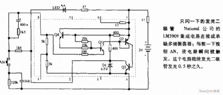
National's LM3909 integrated circuit is connected as the monostable multivibrator; clicking the button AN once will trigger the circuit at the moment. The light emitting diode circuit can falsh for 0.5s.
(View)
View full Circuit Diagram | Comments | Reading(731)
DC strobe light circuit diagram
Published:2011/9/7 2:16:00 Author:Lucas | Keyword: DC strobe light
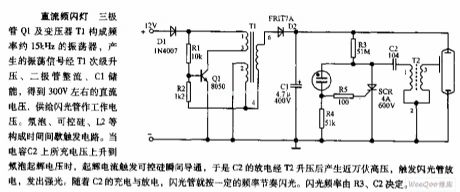
Transistor Q1 and transformer T1 form the oscillator with frequency about 15kHz, and the oscillation signal is boosted by the T1 secondary, rectified by diode, storaged by C1 to be about 300V DC voltage. Neon bulb, SCR, L2, etc. constitute a time interval trigger circuit. When the charging voltage on the capacitor C2 is up to the neon bulb starter voltage, starter current will trigger SCR to get transient conduction, so the discharge of C2 can get ten thousand volts after boosting by T2, then it will trigger the flashing tube to discharge and emit strong light. With the charge and discharge of the C2, the flashing tube will flash at a certain frequency rhythm.
(View)
View full Circuit Diagram | Comments | Reading(2393)
LAN (Ethernet) controlling AD ADC, analog data acquisition module
Published:2011/9/8 3:11:00 Author:Lucas | Keyword: LAN , Ethernet, controlling , AD ADC, data acquisition module

The local area network (Ethernet) controlling AD ADC / analog data acquisition module uses TCP / IP protocol and control host (PC) to communicate, and it is stable and reliable. Transmission distance is far ( it is up to 300 meters through the switch cascaded, even through it can the remote control by the Internet), each AD conversion / data acquisition board is assigned an unique IP address, and it makes data transmission and distinction by IP address; the controlled AD conversion / data acquisition board has a large number (IP address range: 192.168.1. 1 ~ 192.168.1.254, you can drive total of 254 AD conversion / data acquisition boards). The control panel has 6 channels of 10-bit (precision is ± 1LSB) high-speed A / D converter channels.
(View)
View full Circuit Diagram | Comments | Reading(1018)
Local area network remote control stepper motor control module
Published:2011/9/7 2:04:00 Author:Lucas | Keyword: Local area network , remote control , stepper motor, control module
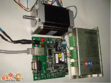
In computer integrated manufacturing (CIM) or industrial automation (IA) area, many long-distance control devices have difficulty in data transmission, and its anti-interference performance is poor,when the multi-audience-bit machine is networking, the software needs to address. For this, we have developed stepper motor control module which based on local area network (Ethernet). The network controlling stepper motor control module uses TCP / IP protocol and controlling host (PC) to communicate, and the operation is stable and reliable. Each stepper motor is assigned an unique IP address, and it can do the transmission distinguish for controlling data by IP address.
(View)
View full Circuit Diagram | Comments | Reading(2253)
Pulse express charger circuit diagram
Published:2011/9/7 7:02:00 Author:Vicky | Keyword: pulse, express charger

Pulse express charger circuit is shown in the above picture. This nickel-cadmium battery charger can reduce undesirable polarization and prolong the lifetime of battery. In the circuit, 555 are connected and form astable vibrator, which is uses as clock with frequency of about 500Hz. The astable vibrator controls decimal counter CD4017 to output square wave pulse. It then conducts high-current pulse charging and discharging with a proportion of 5:1 to the nickel-cadmium battery after amplified by power tube. There are intermittent pauses during the charging and discharging. During the pauses,check the voltage of the battery by the calculating amplifier. When the battery is full charged, the circuit automatically stops charging. (View)
View full Circuit Diagram | Comments | Reading(3283)
Quick 1.5V flashing circuit diagram
Published:2011/8/30 21:06:00 Author:Lucas | Keyword: Quick 1.5V flashing
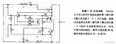
There is an increased 1.5kΩ resistor connected between pin 4 and pin 8 of National's LM3909 IC, and it makes the flashing rate be 2 times quicker than the 300μF capacitor between pin 1 an dpin 2. Changing the connection of external leads can make the resistance of the internal RC circuit select in 3K, 6K or 9K.
(View)
View full Circuit Diagram | Comments | Reading(1021)
Applied circuit diagram of nrf401 wireles receiving and dispatching chip
Published:2011/9/7 6:52:00 Author:Vicky | Keyword: nrf401 wireles receiving and dispatching chip

In this design, wireless radio frequency adopts nrf401 receiving and dispatching chips launched by a Norway company called Nordic. The chip uses 433 mhz ism frequent range. It is the real monolithic uhf wireless receiving and dispatching chip. The 20 pins chip contains high frequency transmitting, high frequency receiving, pll synthetic, fsk modulation, multi-channel chang-over and so on. It is a wireless data transmitting product of the highest integrated level at present. The wireless radio frequency module adopts differential circuit loop-antenna. The load impedance of the antenna end is 380ω. The circuit principle is shown in the above picture. The parameters of the exterior components are listed in the picture, among which, j1 is the interface of the wireless radio frequency module and control module. (View)
View full Circuit Diagram | Comments | Reading(2940)
CAT37 White LED driver circuit diagram
Published:2011/8/25 21:06:00 Author:Lucas | Keyword: White LED driver
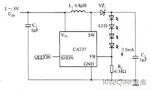
CAT37 is the DC / DC step-up converter with adjustable output current. CAT32's main technical characteristics are as follow. ① Low Quiescent Current: 0.5mA. ② it uses low-resistance (0.5Ω)and high-voltage power switch, and the power efficiency is above 80%. ③ pin configuration is compatible with LT1937. ④ adjustable output current is up to 40mA, which can drive up to four series of white LEDs. ⑤ operating frequency is 1.2MHz, and it can use an external low inductor, capacitor. ⑥ When the input voltage is as low as 2.5V, it also can work. ⑦ Shutdown current is less than 1μA. ⑧it has open load protection.
(View)
View full Circuit Diagram | Comments | Reading(780)
R1211 White LED driver circuit diagram
Published:2011/8/25 21:12:00 Author:Lucas | Keyword: White LED driver
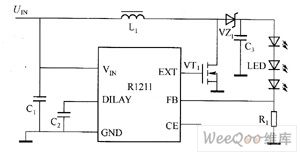
Ricoh's R1211 Series use low-power CMOS technology to produce the switching boost converters with current controlling function. The peripheral circuit is simple, it just needs an inductor, a diode, a FET and a few resistors and capacitors. The input voltage range is 2.5 ~ 5.5V, and it is suitable for single cell lithium-ion battery or ordinary dry battery power supply. The internal parts of the chip uses PWM modulation, which can produce 15V output voltage to drive 3 series white LEDs. The maximum duty cycle of R1211 is 90%. R1212 has a 1.4MHz fixed switching frequency.
(View)
View full Circuit Diagram | Comments | Reading(820)
LT3543 White LED driver circuit diagram
Published:2011/8/25 21:18:00 Author:Lucas | Keyword: White LED driver
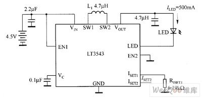
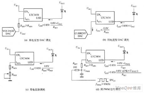
The white LED (ILED = 500mA) driver circuit composed of LT3543 is shown in Figure 1. In Figure 1, the ISET1 end is set a 6.19kΩ resistor, and EN1 is used to control the white LED turning on and off. ISET2 is vacant, and EN2 is ground. White LED in the circuit selects LUMILED company's products LXCLLW3C; inductor L1 is TOKO's A997AS-4R7M. Changing the resistor RISETI of ISET1 side can change the white LED current ILED, that can achieve the dimming purpose by changing the brightness of white LED. The white LED dimming has four methods, which are shown in Figure 2.
(View)
View full Circuit Diagram | Comments | Reading(1185)
LT3466 LED driver circuit diagram
Published:2011/8/31 20:15:00 Author:Lucas | Keyword: LED driver
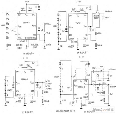
LT3466 is a dual-output full-featured step-up DC / DC converter. The two LED strings can be dimming by each CTRL pin independent control, and the internal PWM dimming system can provide PWM signal for their respective PWM pin, thus dimming range is extended to 1000:1. The LT3486's operating frequency can be set by external resistors, and their range is 200kHz ~ 2MHz. The current detection circuit has the low feedback voltage (200mV) to reduce power consumption of the current-sense resistor and improve the efficiency of the circuit, and it has LED open circuit output voltage limiter function.
(View)
View full Circuit Diagram | Comments | Reading(1646)
Traffic light alternately flashing circuit diagram
Published:2011/8/31 20:36:00 Author:Lucas | Keyword: Traffic light , alternately flashing
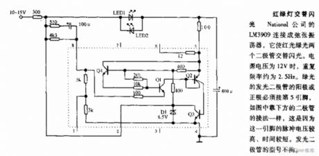
National's LM3909 is connected into relaxation oscillator, which allows two diodes with red light green light alternately flashing. Power supply is 12V, and the repetition rate is about 2.5HZ, then the anode or cathode of green light-emitting diode must be connected to pin 5, and the connection is shown in the bottom, this is because the pulse voltage of the pin is higher, time is shorter. LED models is not limited.
(View)
View full Circuit Diagram | Comments | Reading(976)
Red and green LED flasher circuit diagram
Published:2011/8/31 20:51:00 Author:Lucas | Keyword: Red LED flasher , green LED flasher
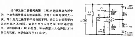
An amplifier in the LM324 quad op amp is connected as a square wave oscillator to make each LED flash once per second. Two light-emitting diode series resistors is different, because they require different forward voltages. If LED2 has low light between the two flashing interval, the resistance R6 can be slightly increased. R6 is too high to reduc LED2's flashing brightness. The supply voltage can be use 5V or 6V.
(View)
View full Circuit Diagram | Comments | Reading(1377)
Simple flashing annunciator circuit diagram
Published:2011/8/30 20:59:00 Author:Lucas | Keyword: Simple flashing annunciator
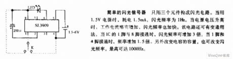
It only uses three components to form the flashing circuit. When it uses 1.5V supply, it consumes 1.5mA, and the flashing frequency is 1Hz. When the supply voltage rises, the operating current increases slightly, and the flashing frequency is accelerated. The circuit also has alternative uses, when the pin 1 of IC is connected to pin 8, the flashing frequency is increased 3 times. When pin 1 is connected pin 4, the frequency is increased 1.5 times. Also changing the capacitor also can change the flashing rate to 1000Hz.
(View)
View full Circuit Diagram | Comments | Reading(1067)
The trigger circuit diagram for teaching demonstration
Published:2011/9/7 22:34:00 Author:Lucas | Keyword: trigger , teaching demonstration
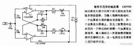
The two amplifiers in LM3900 quad op amp form the bistable multivibrator. When the input is grounded, the output of one op amp becomes conduction, and the other op amp stops, and light-emitting diode indicates which op-amp is conduction at any given moment. Input is grounded again, the flip-flop's state flips over. This circuit is suitable for teaching demonstration in the classroom.
(View)
View full Circuit Diagram | Comments | Reading(990)
CAT32 white LED driver circuit diagram
Published:2011/8/25 21:04:00 Author:Lucas | Keyword: white LED driver
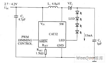
CAT32 is the DC / DC step-up converter with adjustable output current. CAT32's main technical characteristics are as follow. ① Low Quiescent Current: 0.5mA. ② it uses low-resistance (0.5Ω)and high-voltage power switch, and the power efficiency is above 80%. ③ pin configuration is compatible with LT1932. ④ adjustable output current is up to 40mA, which can drive up to four series of white LEDs. ⑤ operating frequency is 1.2MHz, and it can use an external low inductor, capacitor. ⑥ When the input voltage is as low as 2.0V, it also can work. ⑦ Shutdown current is less than 1μA. ⑧it has open load protection.
(View)
View full Circuit Diagram | Comments | Reading(1042)
CP2126 white LED driver circuit diagram
Published:2011/8/25 20:59:00 Author:Lucas | Keyword: white LED driver
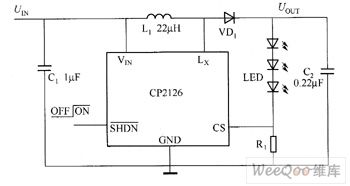
CP2126 is the boost DC / DC converter which uses constant current to drive white LED. CP2126's main technical characteristics are as follow. ① the 3.2V power supply can drive four series of white LEDs. ② high efficiency: 85% (typical value). ③ it only needs 0.22μF output capacitor. ④ stable 20V bipolar switch. ⑤ working switching frequency is 900kHz, and it can the small inductor with the height in only 1mm. ⑥ working temperature environment meets the industry-standard: -40 ~ 85 ℃. ⑦it uses flat SOT23-5L package.
(View)
View full Circuit Diagram | Comments | Reading(731)
T6321A/T6325A White LED driver circuit diagram
Published:2011/8/29 3:05:00 Author:Lucas | Keyword: White LED driver
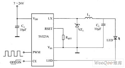
T6321A has a wide voltage input range, and conversion efficiency can reach 80%, and it has the fatures of stable work, strong anti-interference, simple circuit, thermal performance (the bottom of the IC has the cooling chip to reduce the core temperature in 10 ℃ and extend the life of the IC) and so on. T6321A's main technical characteristics are as follow. ① constant current output: 350mA. ② Input DC voltage range: 6.0 ~ 18V. ③ Package Type: SOT23-3. ④ Operating Temperature: -40 ~ +85 ℃. ⑤ Maximum soldering temperature: 260 ℃.
T6325A's main technical characteristics are as follow. ① Input Voltage: 7 ~ 24V. ② constant current output: the maximumvalue is 700mA. ③ Temperature: -40 ~ +85 ℃. ④ Maximum soldering temperature: 300 ℃.
(View)
View full Circuit Diagram | Comments | Reading(1041)
LTC3490 white LED driver circuit diagram
Published:2011/9/6 4:33:00 Author:Lucas | Keyword: white LED driver
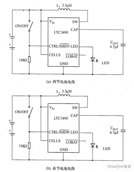
LTC3490 is a synchronous current-mode step-up converter with fixed frequency. In the two-cell application circuit, LTC3490's efficiency is up to 90%; in the application of single cell circuit, LTC3490's efficiency is higher than 70%. The Figure shows the LTC3490's two-battery circuit and single-cell circuit. In the circuit, when the output voltage is higher than 4.5V, the over-voltage detector will force the LTC3490 into shutdown mode, and over-voltage detector remains connection state, when the output voltage is down below to 4.5V, it starts the normal work.
(View)
View full Circuit Diagram | Comments | Reading(1276)
| Pages:502/2234 At 20501502503504505506507508509510511512513514515516517518519520Under 20 |
Circuit Categories
power supply circuit
Amplifier Circuit
Basic Circuit
LED and Light Circuit
Sensor Circuit
Signal Processing
Electrical Equipment Circuit
Control Circuit
Remote Control Circuit
A/D-D/A Converter Circuit
Audio Circuit
Measuring and Test Circuit
Communication Circuit
Computer-Related Circuit
555 Circuit
Automotive Circuit
Repairing Circuit