
Circuit Diagram
Index 518
The booster and electric charge pump converter drive LED application circuit
Published:2011/8/23 22:07:00 Author:Borg | Keyword: booster, electric charge, pump converter
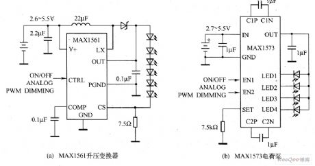
In the figure, there are two projects, MAX1561 booster converter and MAX1573 pump, to drive the LED, and the complexes of the two circuits are almost the same, i.e both of the two circuits have several simple elements, but the booster converter needs inductors and Schottky diodes(some booster converters integrate the Schottky diode inside themselves, but the efficiency is often low), and the electric charge pump circuit doesn't need the inductor.
(View)
View full Circuit Diagram | Comments | Reading(1449)
The LED circuit driven by the regulated electric charge pump
Published:2011/8/21 21:38:00 Author: | Keyword: electric charge pump, LED

SP6682 regulated electric charge pump drive LED circuit is shown in the figure. SP6682 includes an internal 500KhZ oscillator, which is used to drive the pump capacitance normally and double the input voltage. In the figure, the circuit is not adopting with the pump capacitor, but adding the oscillator output on the 7-pin and driving VT conduction and breakdown. VT1, L1, VD1 and C1 compose a booster regulator, which can raise the voltage on the two poles of C. When the voltage surpasses the LED forward voltage drop, the current is starting to run.
(View)
View full Circuit Diagram | Comments | Reading(851)
The circuit of controlling the LED dimmer by changing LED forward current
Published:2011/8/23 22:07:00 Author:Borg | Keyword: LED dimmer, LED forward current

Either MAX5362 with I2C connector or MAX5365 with SP1 can provide with 32-stage brightness adjustment, see as the figure. As the forward current may affect the color coordinates, so the LED white light changes with the change of the brightness, but the same forward current will makes every LED glow the same light. The circuit of controlling the LED dimmer by changing LED forward current is shown in the figure.
Figure The circuit of controlling the LED dimmer by changing LED forward current
(View)
View full Circuit Diagram | Comments | Reading(814)
A highly concentrated pump dual-display white light LED drive circuit
Published:2011/8/23 22:07:00 Author:Borg | Keyword: dual-display, LED drive, pump

The driving pin of LM27965 dual-display white light LED drive is divided into 3 independent control banks. The first can be equipped with 4~5 white light LED, which is used to provide back light for the large screen; the second can be equipped with 2~3 white light LED, which is used to provide light for smaller affiliated display; the other controls the white light LED drive independently, which is used to drive the indicator or general LED. LM27965 is a connector which is compatible with I2C which allows the LED brightness of each team to be controlled independently.
(View)
View full Circuit Diagram | Comments | Reading(626)
A low-noise, frequency-fixed drive white light LED circuit
Published:2011/8/23 22:08:00 Author:Borg | Keyword: low-noise, frequency-fixed, white light LED

CP2128 is a low-noise, frequency-fixed booster DC/DC converter, under the condition that the voltage is 2.7~4.5V, the device is outputting a voltage os 5V, its max output current can reach 100mA. Cp2128 needs very few external elements, so it is suitable for micro and batter-powered conditions. CP2128 can reduce the output and input drift from zero to full load. CP2128 has the over-heat protection function, which can afford the continuous UOUT ground connection.
(View)
View full Circuit Diagram | Comments | Reading(714)
The multi-function ultrasonic humidifier circuit
Published:2011/8/23 22:08:00 Author:Borg | Keyword: multi-function, ultrasonic humidifier
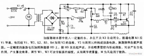
When there is some water in the humidifier, the water level switch K2 is pulling in automatically. When the power supply K1 is put through, the voltage is added on the base electrode of V2 by V1, W2, L2, R3 and R4, V2 forms the oscillator with its external elements, the oscillator frequency is in ultrasonic waveband. When the oscillating voltage of certain amplitude is added on the converter HD, HD will generate the ultrasonic wave, and is will form resonance in the fog tube, which has some effect on water and fog is generated. By adjusting W1 and W2, the amplitudes of W1 and W2 can be changed, so the fog content is adjusted.
(View)
View full Circuit Diagram | Comments | Reading(4535)
The electronic frostbite instrument circuit
Published:2011/8/23 22:11:00 Author:Borg | Keyword: electronic, frostbite instrument
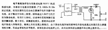
The electronic frostbite instrument special integrated circuit SL9711 forms the oscillating circuit, power amplifier circuit and controller, it generates the sine waves of 10Hz and 3Hz, after it is boosted by the transformer, the current is adjusted by the potentiometer. As there are diodes in the output, so the shape of the current running through human body is the impulse current. When it is working on the human body, the motor nerves cause the muscle shake due to the stimulation. In several seconds, the palsy feel is gone, the feeling and motor nerves are starting to turn into the impedance state, the anti-pain effect is appearing as the pain valve is rising up.
(View)
View full Circuit Diagram | Comments | Reading(692)
The Sound and light double control eight-channel color light 12 songs sound circuit (BH-SH-II)
Published:2011/8/30 2:24:00 Author:Christina | Keyword: Sound, light, double control, eight-channel, color light, 12 songs, sound circuit

As the figure shows, it is composed of the voice-activated electronic switch, the light control switch, the music sound circuit, the audio power amplifier circuit, the multivibrator, the time order distribution circuit, the audio control switch circuit, the SCR drive circuit and the AC step-down rectifier circuit. When the circuit is playing the world famous songs, the eight-channel color light will send out the synchronous flash light.
(View)
View full Circuit Diagram | Comments | Reading(683)
The OTL power amplifier circuit made of TDA2030A
Published:2011/8/23 22:11:00 Author:Borg | Keyword: power amplifier, OTL

The OTL power amplifier is powered by a single supply and it is fixed with an output coupling capacitor. See as the figure, R5 (150 kΩ) and R4 (4.7 kΩ) decide the gain of the amplifier closed loop, the lower the resistance of R4 is, the higher the gain will be, but high gain can lead to the distortion of the signal. The 2 LEDs are connected between the power supply and the output terminal, which is used to prevent the inverting of the loudspeaker inductance load from affecting the sound quality, C3(0.22 uF) and R6(1 Ω) are used to compensate the phase of the inducting load (loudspeaker), so the self-motivation is gone, the circuit is powered by a 36V single power supply.
(View)
View full Circuit Diagram | Comments | Reading(3542)
Deep well water level detection sound and light alarm circuit
Published:2011/8/30 2:31:00 Author:Christina | Keyword: Deep well, water level, detection, sound, light, alarm circuit

As the figure shows, it is composed of the conductive type probe, the electronic switch and the frogs sound circuit. It can be used in the detection of the water level of the wells or mines, when the probe touches the groundwater, the light-emitting diode will send out the green light, and the circuit will output the sound of forgs. The circuit is simple and practical, the volume is small and exquisite.
(View)
View full Circuit Diagram | Comments | Reading(1458)
The OTL power amplifier circuit composed of TDA2030A
Published:2011/8/23 22:11:00 Author:Borg | Keyword: power amplifier, OTL

The OCL power amplifier type is to use dual power supply without any coupling capacitor, see as the figure, as there is no output coupling capacitor, the low frequency reaction is improved, so it is a hi-fi circuit. The dual power supply is fixed with a transformer whose primary coil middle point is connected with the ground and the voltages of the upper and lower are symmetric, after being rectified and filtered, a ±18V dual power supply is formed, whose output power is 20W.
(View)
View full Circuit Diagram | Comments | Reading(1026)
The BTL power amplifier circuit made of TDA2030A
Published:2011/8/23 22:12:00 Author:Borg | Keyword: BTL, power amplifier

The main features of BTL are as follows: it consists of 2 power amplifiers of the same functions, and the input signals are inverting. In fact, both the inverting input and non-inverting input are used to make sure the input signals are inverting, at the same time, their amplitudes are the same, so the requirement of BTL circuit can be satisfied. The circuit is shown in the figure, after R7(1 kΩ) and R8(33 Ω) distribute the signal, the attenuating times are equal to the amplified times of U1, and the attenuated signal is added on the inverting terminal of U2 by R5.
(View)
View full Circuit Diagram | Comments | Reading(3379)
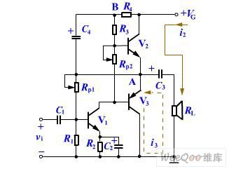
The single power supply amplifier circuit with a bootstrap circuit
Published:2011/8/23 22:12:00 Author:Borg | Keyword: single power supply, amplifier, bootstrap circuit

The single power supply amplifier circuit with a bootstrap circuit is shown in the figure.
(View)
View full Circuit Diagram | Comments | Reading(1588)
The upper limit and lower limit temperature control audio alarm circuit MAX6502/3
Published:2011/8/30 2:33:00 Author:Christina | Keyword: upper limit, lower limit, temperature control, audio, alarm circuit

View full Circuit Diagram | Comments | Reading(714)
The voltage amplifier circuit of the electric charge amplifier
Published:2011/8/23 22:13:00 Author:Borg | Keyword: voltage amplifier, electric charge amplifier

The voltage amplifier circuit of the electric charge amplifier The feature of the the electric charge amplifier is the wide frequency band. In the backward feedback circuit, as the distributing circuit determines the gain, the signal is stabilized by the cable capacitor output by the sensor. This amplifier consists of the high gain op-amp and backward feedback capacitor, and the lower limit frequency is decided by C1 and R1.
(View)
View full Circuit Diagram | Comments | Reading(902)
Excessive carbon monoxide automatic exhaust voice alarm circuit
Published:2011/8/30 2:46:00 Author:Christina | Keyword: Excessive carbon monoxide, automatic exhaust, voice, alarm circuit

As the figure shows, it is composed of the gas sensor, the solid-state language circuit, the monostable timing circuit, the SCR trigger exhaust fan circuit, the AC step-down rectifier circuit. It can be used in the room which burns the coal, when the coal is not fully burned, the harmful gas such as the carbon monoxide will exceed the standard, the circuit will open the exhaust fan automatically, and it will send out the voice of The carbon monoxide exceeds the standard, please be careful of the gas poisoning to ensure the personal safety.
(View)
View full Circuit Diagram | Comments | Reading(1323)
The thermocouple isolated amplifier circuit
Published:2011/8/23 22:13:00 Author:Borg | Keyword: thermocouple, isolated amplifier
Working principles: Q1 is the pre-amplifier tube, which is using the NPN silicon tube, its temperature stability is good. To reduce the noise, the front stage is the key, or the noise will be noticeable after it is amplified at the following stages. The most importance is to avoid the noise being input from the base electrode. In this circuit, the base electrode power supply of Q1 is got after it is stabilized by D1 and D2, which improves the stability further. The resistance of the emitter resistor R4, which has little effect on the stable and still working point, it fulfills the function of AC backward feedback. (View)
View full Circuit Diagram | Comments | Reading(1005)
Three-diode rectification energy consumption braking circuit
Published:2011/8/30 2:56:00 Author:Christina | Keyword: Three-diode, rectification, energy consumption, braking circuit

As the figure shows, when you press the STP, the AC contactor KM will loss the electrical energy and release, the KMB and KT get the electrical energy to act immediately, the two groups of main contactor of KMB will make the three-phase winding wire of the electromotor M get into the short circuit state, the other three groups of main contactor introduce the three-phase half wave rectifying power supply to make the stator winding of the electromotor M connect into the symmetrical parallel line, so we achieve the purpose of braking. Then the KT cuts off, the KMB losses the electrical energy to release, the braking is over. R is the limiting resistor.
(View)
View full Circuit Diagram | Comments | Reading(1023)
The circuit of piezoelectric accelerator being used in impact test
Published:2011/8/23 22:12:00 Author:Borg | Keyword: piezoelectric accelerator, impact test

In the figure, GA1 sensor is a plastic piezoelectric accelerating sensor which is made of PVDF and other materials. It can be used in the impact test device when it is combined with the following circuit. The circuit consists of the proportion amplifier, voltage comparator and LEV converter. When the impact reaches certain value, the comparator A2 is outputting a switch volume signal, after the single steady trigger composed of 555 is driven by triode BG, the LED light is glowing, and the buzzer is driven. (View)
View full Circuit Diagram | Comments | Reading(1038)
The voltage amplifier circuit of the piezoelectric accelerator
Published:2011/8/23 22:13:00 Author:Borg | Keyword: voltage amplifier, piezoelectric accelerator

The voltage amplifier circuit of the piezoelectric accelerator
The voltage amplifier is an amplifier circuit with a high input impedance, as the capacitance change of the sensor output cable will make the output voltage change with it, so R is often used in the piezoelectric accelerating sensor with an amplifier inside it.
(View)
View full Circuit Diagram | Comments | Reading(691)
| Pages:518/2234 At 20501502503504505506507508509510511512513514515516517518519520Under 20 |
Circuit Categories
power supply circuit
Amplifier Circuit
Basic Circuit
LED and Light Circuit
Sensor Circuit
Signal Processing
Electrical Equipment Circuit
Control Circuit
Remote Control Circuit
A/D-D/A Converter Circuit
Audio Circuit
Measuring and Test Circuit
Communication Circuit
Computer-Related Circuit
555 Circuit
Automotive Circuit
Repairing Circuit