
Circuit Diagram
Index 506
High pressure sodium lamp electronic ballast circuit diagram
Published:2011/9/5 3:35:00 Author:Lucas | Keyword: High pressure , sodium lamp , electronic ballast

The circuit uses UC3854B as the control chip to establish an active power factor correction circuit with fixed frequency average current-mode, and the circuit is shown as the figure. In the figure, rectifier bridge B1, inductor L1, power switching device S1, boost diode D1, output filter capacitor C1 and resistor R1 form a current sampling PFC circuit. UC3854B provides all the active power factor correction features, which include voltage amplifier, analog multiplier / divider, current amplifier and a fixed frequency PWM, in addition, they also contain power MOSFET gate driver, 7.5V reference voltage, bus predictor, and over-current comparator.
(View)
View full Circuit Diagram | Comments | Reading(3111)
Electronic ballast circuit diagram for fluoresent lamp
Published:2011/8/29 3:15:00 Author:Lucas | Keyword: Electronic ballast , fluoresent lamp

The electronic ballast circuit for fluorescent lamp is composed of the rectifier filter circuit, high-frequency oscillator circuit and output circuit. In the circuit, the rectifier filter circuit consists of the rectifier diodes VD1- VD4 and filter capacitors C1, C2; high-frequency oscillator consists of the transistors vi, V2, resistors R1-R7, capacitors C3, C4, C6, diodes VD5- VD8 and high frequency transformer T (W1-W3 are wound on the same magnetic ring to form a high-frequency transformer); output circuit is composed of the chokes L1, L2 and capacitors C1-C10.
(View)
View full Circuit Diagram | Comments | Reading(3477)
object motion path distinguishmen circuit
Published:2011/9/6 23:44:00 Author:chopper | Keyword: motion path, distinguishmen circuit
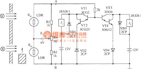
Puttwo photoresistors who have the similar resistance and performance on the same side of the object motion path at theappropriate distance.Settwo light sourceson the relative position of the other side respectively, so that objects can move in a straight line between the light source and photosensitive resistor. Using the circuit shown in picturecan determine the direction of motion path. Circuit is formed by the bridge and polarity distinguishment. Rs1, Rs2, R1, R2, and Rw form the bridge and power supply E0 offers the power,and endsA, B output. (View)
View full Circuit Diagram | Comments | Reading(1579)
MAX1912 white LED driver circuit diagram
Published:2011/8/29 3:46:00 Author:Lucas | Keyword: white LED driver

White LED power supply provides a sufficiently high output voltage, and the white LED connected in parallel is added the same current. If all the connected white LEDs in parallel has the same current, then all the white LEDs will have the same color coordinates. Maxim's MAX1912 charge pump with current control can achieve this goal. The circuit using MAX1912 to drive 3 parallel LEDs is shown as the gigure, MAX1912 charge pump has a large range, and it can increase the input voltage to 1.5 times.
MAX1912contains thecharge pumpand the current control circuit, and the charge pump provides sufficient voltage for the white LED driver.
(View)
View full Circuit Diagram | Comments | Reading(818)
MAX8631X white LED driver circuit diagram
Published:2011/8/29 3:38:00 Author:Lucas | Keyword: white LED driver

MAX8631X charge pump's main technical features are as follow. ① It can drive eight white LEDs. ② 30mA drive current is used for backlight. ③ 400mA total drive current is used for the flash. ④ two built-in low noise 200mA LDO. ⑤ It can maintain the 94% highest conversion efficiency and the 85% average conversion efficiency in the effective lithium-ion battery supply voltage range (η = PLED / PABT). ⑥ 0.2% current matching accuracy. ⑦ It has adaptive 1x mode, 1.5x mode, 2-fold pressure mode switching function. ⑧ It has flexible brightness control. ⑨It has single, serial-pulse interface (32).
(View)
View full Circuit Diagram | Comments | Reading(910)
MAX8630Y / MAX8630Z white LED driver circuit diagram
Published:2011/8/29 3:27:00 Author:Lucas | Keyword: white LED driver

MAX8630Y/MAX8630Z charge pump's main technical features are as follow. ①It can maintain the 93% highest conversion efficiency and the 85% average conversion efficiency (η = PLED / PBAT) in the effective lithium-ion battery supply voltage range. ② 1% current matching accuracy. ③ The total drive current is up to 125mA. ④It has adaptive 1x mode, 1.5x mode switching function. ⑤ The single, burst dimming (MAX8630Z). ⑥The main screen and sub-screen has the separate opening and closing control and brightness adjustment. ⑦ linear regulator rating: full value, 31/32, 30/32, 1 / 32. ⑧ direct PWM dimming (MAX8630Y).
(View)
View full Circuit Diagram | Comments | Reading(803)
MAX1595 white LED driver circuit diagram
Published:2011/8/29 3:41:00 Author:Lucas | Keyword: white LED driver

Its unique control structure allows the input voltage boost or buck converter to maintain a stable output voltage. MAX1595 charge pump's main technical characteristics are as follow. ① It requires only three external ceramic capacitors. ② It does not need inductance. ③The output current is up to 125mA. ④ The stable output voltage accuracy is ± 3%. ⑤ 1MHz switching frequency. ⑥ 1.8 ~ 5.5V input voltage range. ⑦ 220pA quiescent current. ⑧ 0.1μA shutdown current. ⑨ In shutdown mode, the load can be disconnected.
(View)
View full Circuit Diagram | Comments | Reading(973)
24V converting to 12V switching power supply circuit diagram
Published:2011/9/5 3:43:00 Author:Lucas | Keyword: switching power supply

The 24V diesel vehicles is fitted with 12V electrical appliances (such as instruments, cassette players, fans, etc.), usually it uses 12V three-terminal regulator. However, due to voltage drop on the regulator is up to 12V, the power dissipation and temperature is too high to be damaged easily. We design a switching power supply transformer which can reduce 24V voltage to 12V, and the circuit is shown as the figure. This circuit uses 555 as a pulse oscillator. Pin ⑤ of 555 is connected to a regulator to obtain the +6 V reference voltage, and pin ② gets the sample voltage from the sampling circuit composed of R7, R8. When the pin voltage of pin ② is less than +3 V, pin ③ outputs high, so BG3, BG1, BG2 are saturated conduction and provide voltage for the load.
(View)
View full Circuit Diagram | Comments | Reading(2727)
DC-AC conversion circuit control circuit diagram
Published:2011/9/5 4:08:00 Author:Lucas | Keyword: DC-AC conversion, control circuit

In the figure, the TL494 is used as the core to form the PWM driver and protection circuit, and the changing frequency is 50kHz. 115V output voltage is sent to P8 after stepping-down and isolating, then it is sent to TL494 error amplifier A1 after getting RMS by passing AD536, and it is used as the system's closed-loop voltage control. The current of push-pull inverter circuit is sent to control panel to do signal processing by P7 after passing current transformer sampler, then it is sent to the TL494 error amplifier A2 as the current-loop control system. TL494 outputs driver signal is amplified by passing P6, then it is sent to the main board.
(View)
View full Circuit Diagram | Comments | Reading(3328)
Flower nursery water shortage automatic irrigation control and voice alarm circuit
Published:2011/9/5 21:19:00 Author:TaoXi | Keyword: Flower nursery, water shortage, automatic irrigation, control, voice alarm circuit

View full Circuit Diagram | Comments | Reading(1022)
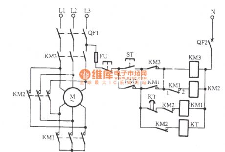
Boiler induced draft fan circuit (1)
Published:2011/9/5 21:53:00 Author:TaoXi | Keyword: Boiler, induced draft fan
View full Circuit Diagram | Comments | Reading(826)
Photosensitive tracking control circuit
Published:2011/9/6 1:42:00 Author:TaoXi | Keyword: Photosensitive tracking, control circuit

The atmospheric pressure regulating equipments always use the tracking control circuit which is composed of the photosensitive battery BPY11. When both of the two photosensitive batteries are irradiated by the light, there is no base current in the input transistor, they are similar to two phototransistors which are in the cut-off state, the electric motor has no current. If a photosensitive cell is not irradiated by the light, the corresponding edge half-amplifier will conduct, the electric motor turns left or right. The last stage diode group can be used to protect the transistor to prevent the damage. The photosensitive signal can be adjusted by the 10MΩ potentiometer.
(View)
View full Circuit Diagram | Comments | Reading(729)
Light control type electric fan natural wind simulation and music vocal accompaniment control circuit (CD4022)
Published:2011/9/6 2:13:00 Author:TaoXi | Keyword: Light control type, electric fan, natural wind, simulation, music, vocal accompaniment, control circuit

The circuit is as shown in the figure. It is composed of the relaxation oscillator, the light control pulse counting/decoding circuit, the SCR control motor speed control circuit, the music sound circuit and the AC step-down rectifier circuit. Under the strong light, the control circuit starts the fan to blow out the natural wind, and it broadcasts 16 world famous songs.
(View)
View full Circuit Diagram | Comments | Reading(1422)
Infrared automatic door controller circuit
Published:2011/9/5 20:48:00 Author:TaoXi | Keyword: Infrared, automatic door, controller circuit

The infrared receiving and motor driver circuit is as shown in figure 1, when there is no one, the infrared receiver receives the infrared beam which is from the other side. You can fix it one the wall by using the 60mm guide tube which can insert the infrared tube exactly (figure 3), the height is appropriate, and it aims at the opposite receiver, so the infrared ray is not easy to interfere another receiver. The installation method is as shown in figure 4. The signal is amplified and filted by BG6, BG7 and CR to output the low level, the BG5 cuts off.
(View)
View full Circuit Diagram | Comments | Reading(1239)
Pulse sound and light display circuit diagram
Published:2011/9/5 3:51:00 Author:Lucas | Keyword: Pulse , sound and light , display

Sensor is composed of the photosensitive resistors R1, R2, of which R1 is used to collect the amount of light transmission from the tip of finger, R2 is an automatic correction device. The resistors R1, R2 are transferred to equal conditions in advanced, the interference will generate the same resistance changes on the R1, R2, so the error caused by the work environment will cancel by each other. Shaping amplifier uses CD4069 to form the conventional 6-stage amplifier circuit. CD4011 forms the audio oscillator, piezoelectric sound, light emitting diode indicator.
(View)
View full Circuit Diagram | Comments | Reading(1301)
Hualing BCD182 refrigerator control circuit
Published:2011/9/5 20:56:00 Author:TaoXi | Keyword: Hualing, refrigerator, control circuit


The Hualing BCD182 refrigerator control circuit is as shown in the figure. The button switches 1SB and 2SB are controlled by the refrigerating door and freezer dorr of the refrigerator respectively. When the door closes, the button switch closes too; When the door opens, the button switch cuts off. When the power is connected, the timing motor MT, the fan electromotor M1 and the compression motor M2 get power to operate. The refrigerator starts to refrigerate. The current loop is:
(View)
View full Circuit Diagram | Comments | Reading(784)
Haier BC-118 kitchen cold storage refrigerator circuit
Published:2011/9/5 21:23:00 Author:TaoXi | Keyword: Haier, kitchen, cold storage, refrigerator circuit

XP-power plug ST-Temperature controller SB-Door switch EL-Light M1-Fan motor FT-over-current protector M2-compressor PTC-Starter
C-capacitor
(View)
View full Circuit Diagram | Comments | Reading(2523)
Over-voltage automatic power off device
Published:2011/9/5 21:32:00 Author:TaoXi | Keyword: Over-voltage, automatic, power off device


The circuit principle is as shown in the figure. The 220V city electricity supplies the stable 12V operating voltage to the switch integrated circuit through the C1, VD1 and DW1, the partial voltage sampling circuit is composed of the VD3, R2 and RP1. When the city electricity voltage is normal, the DW2 can not conduct, the operating voltage of the TWH8778's pin-5 is lower than 1.6V, the relay J will not close, the city electricity supplies power to the socket CZ through J-1; when the city electricity voltage is higher than the normal value, the DW2 is conducted, the electric potential of the TWH8778's pin-5 rises to 1.6V, the IC turns, the pin-3 outputs the high level, the relay closes, the power supply of the electrical appliance is cut off to avoid the damage.
(View)
View full Circuit Diagram | Comments | Reading(880)
Rolling code coding radio transmitting circuit
Published:2011/9/5 21:37:00 Author:TaoXi | Keyword: Rolling code, coding, radio transmitting

The TDA5100 is designed as the Uhf radio transmitting circuit which is produced by the Siemens company, the internal structure is complex, the function is perfect, the sensitivity is high, the output signal amplitude is wide, the external components are few, the price is cheap, it is the superior performance transmitting circuit.
(View)
View full Circuit Diagram | Comments | Reading(1334)
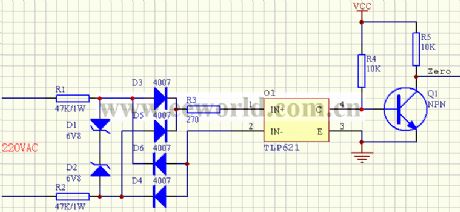
Recognized zero-crossing pulse circuit
Published:2011/9/6 1:05:00 Author:TaoXi | Keyword: Recognized, zero-crossing pulse
View full Circuit Diagram | Comments | Reading(825)
| Pages:506/2234 At 20501502503504505506507508509510511512513514515516517518519520Under 20 |
Circuit Categories
power supply circuit
Amplifier Circuit
Basic Circuit
LED and Light Circuit
Sensor Circuit
Signal Processing
Electrical Equipment Circuit
Control Circuit
Remote Control Circuit
A/D-D/A Converter Circuit
Audio Circuit
Measuring and Test Circuit
Communication Circuit
Computer-Related Circuit
555 Circuit
Automotive Circuit
Repairing Circuit